Cavity type solar heat absorber provided with optical window

A solar heat absorber and optical window technology, applied in the field of solar energy, can solve the problems of high local temperature of the heat absorber, prone to burn-through, uneven distribution of solar radiation heat flow, etc., to reduce temperature gradient and reduce overheating The probability of spotting and thermal stress concentration, the effect of increasing the internal absorption area

Inactive Publication Date: 2010-05-12
HARBIN INST OF TECH
View PDF0 Cites 39 Cited by
  • Summary
  • Abstract
  • Description
  • Claims
  • Application Information

AI Technical Summary

Problems solved by technology

[0003] The invention provides a cavity-type solar heat absorber with an optical window in order to solve the problem that the heat flow of solar radiation absorbed by the existing solar heat absorber is unevenly distributed, resulting in an excessively high local temperature of the heat absorber and easy occurrence of burn-through.

Method used


Image

  • Cavity type solar heat absorber provided with optical window
  • Cavity type solar heat absorber provided with optical window
  • Cavity type solar heat absorber provided with optical window

Examples


specific Embodiment approach 1

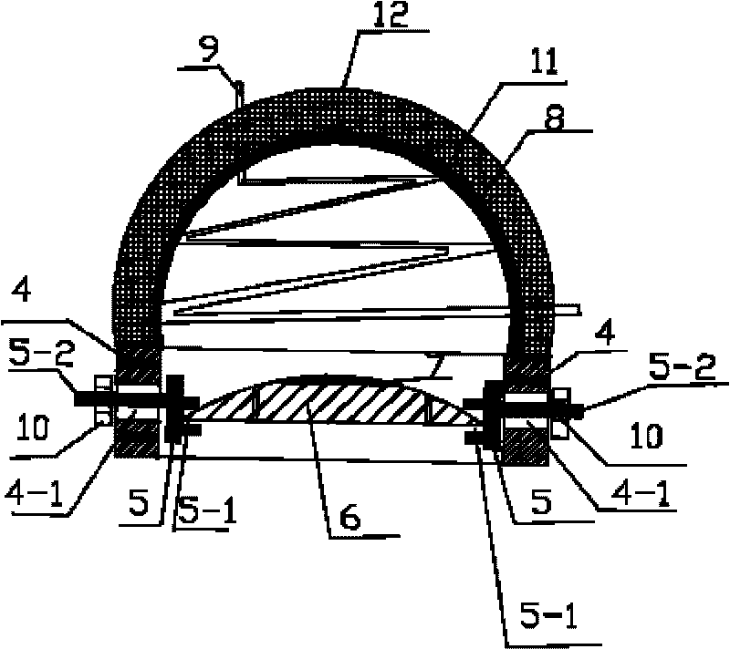
[0007] Specific implementation mode one: combine figure 1 Describe this embodiment, this embodiment comprises heat absorber 8 and heat absorption pipe 9, and described heat absorption pipe 9 is inserted into the cavity of heat absorber 8, and heat absorption pipe 9 follows the inner cavity shape of heat absorber 8 The disk is placed on the inner wall of the heat absorber 8, the shape of the inner cavity of the heat absorber 8 is hemispherical, and it also includes an upwardly convex optical glass body 6 and a guard plate 4, the heat absorber 8 is a hollow body, and the guard plate 4 The protective plate 4 is fixed on the inlet of the heat absorber 8, and the convex optical glass body 6 is arranged on the protective plate 4. The surface of the upward convex optical glass body 6 facing the entrance of the heat absorber 8 is a convex surface, facing away from the absorber. The inlet surface of the heater 8 is a plane.

[0008] The protective plate 4 in this embodiment is a part ...

specific Embodiment approach 2

[0009] Embodiment 2: The difference between this embodiment and Embodiment 1 is that it also includes an adjustable movable bolt 5 and a nut 10, and the adjustable movable bolt 5 includes a U-shaped notch 5-1 and a screw rod 5-2 , two grooves 4-1 are arranged on the circumferential wall of the guard plate 4, the grooves 4-1 are distributed along the axial direction of the guard plate 4, and the two grooves 4-1 are respectively arranged in the diameter direction of the guard plate 4 The two ends of the two ends, the screw 5-2 of the adjustable movable bolt 5 is inserted into the groove 4-1 of the guard plate 4, the U-shaped notch 5-1 of the adjustable movable bolt 5 contains the edge of the convex optical glass body 6, and the screw The cap 10 is screwed on the outer end of the screw 5-2.

[0010] The working principle of the adjustable movable bolt 5 described in this embodiment is: when adjusting the position of the convex optical glass body 6, first unscrew the nut 10, and t...

specific Embodiment approach 3

[0011] Embodiment 3: The difference between this embodiment and Embodiment 1 is that the convex surface of the convex optical glass body 6 is covered with a heat-resistant anti-reflection film 7 .

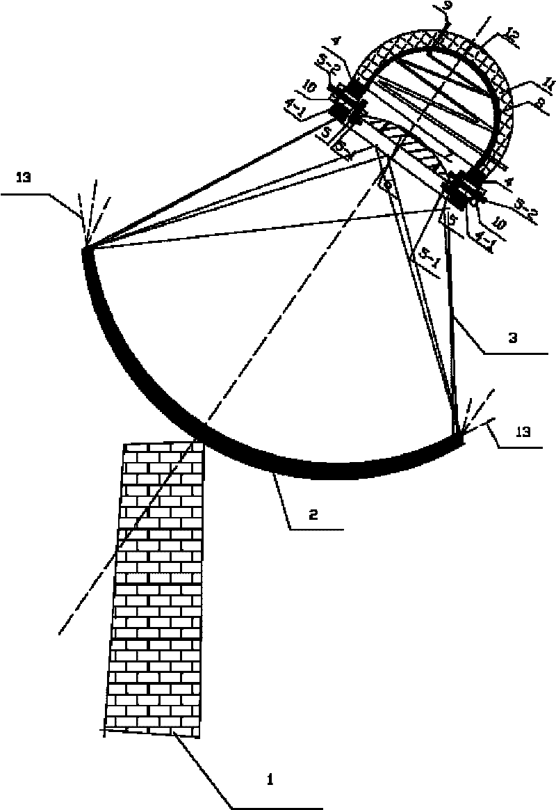
[0012] In this embodiment, the convex surface of the convex optical glass body 6 may be covered with a heat-resistant anti-reflection film 7 as required. When the solar radiation heat flow 13 passes through the convex optical glass body 6 above the heat absorber 8, the The heat-resistant anti-reflection film 7 can enhance the absorbed solar radiation heat flow 13 and prevent the loss of heat flow of the heat absorber 8 body.


PUM


Abstract

The invention relates to a cavity type solar heat absorber provided with an optical window, which relates to the technical field of solar energy and aims to solve the problems that the solar energy radiant heat flows absorbed by the conventional solar heat absorber are not distributed evenly so that the heat absorber has an over-high local temperature and is easy to be burnt through. The cavity type solar heat absorber comprises the heat absorber and heat absorbing tubes; the heat absorbing tubes are coiled up on the internal wall of the heat absorber according to the shape of the inner cavity of the heat absorber; and the shape of the inner cavity of the heat absorber is semi-spherical. The cavity type solar heat absorber also comprises an upward convex optical glass body and a protecting sheet; the heat absorber is a hollow cavity body; the protecting sheet is annular and is fixed on an inlet of the heat absorber; the upward convex optical glass body is arranged on the protecting sheet; and an inlet surface of the upward convex optical glass body facing the heat absorber is a convex surface, while an inlet surface backing on to the heat absorber is a flat surface. The cavity type solar heat absorber can efficiently receive radiant heat and transfer heat to working fluids so as to reduce local high temperatures and thermal stress concentrations on the wall surfaces of the heat absorbing tubes. The cavity type solar heat absorber can be widely used in the field of solar heat absorbers.

Description

technical field [0001] The invention relates to the technical field of solar energy, in particular to a cavity type solar heat absorber with an optical window. Background technique [0002] At present, the solar thermal absorber is the core component of the thermal power generation system, which converts the energy of sunlight into the heat energy of the working fluid. Since the heat absorber has been working under high-density and changing radiation heat flow conditions for a long time, its working environment is very harsh, and the heat flow distribution of the concentrated solar focal spot is uneven in space and time, resulting in a large thermal stress on the surface of the heat absorber and heat absorption. When the local temperature of the heat sink is too high, damages such as local burn-through are also prone to occur, which will seriously affect the safe and stable operation of the heat sink. Both Solar One power station in the United States and CESA-I power statio...

Claims


Application Information

Patent Timeline
Patent Type & Authority Applications(China)
IPC IPC(8): F24J2/12F24J2/24F24S23/71F24S10/70
CPCY02E10/42Y02E10/44
Inventor 帅永夏新林谈和平张晓晨袁远王富强
Owner HARBIN INST OF TECH
Why Eureka
Try Eureka