Image encoding apparatus and method of controlling same

a technology of image data and encoding apparatus, applied in the field of image encoding apparatus, can solve the problem that the decline in image quality will not be visible, and achieve the effect of suppressing the decline in image quality and high compression efficiency

Inactive Publication Date: 2011-09-20
CANON KK
View PDF15 Cites 1 Cited by
  • Summary
  • Abstract
  • Description
  • Claims
  • Application Information

AI Technical Summary

Benefits of technology

[0009]The present invention has been devised in view of the above-mentioned problems and provides a technique whereby even an image that is a mixture of images having different attributes, such as a character or line-drawing image and a natural image, etc., is encoded in accordance with the respective attributes, thereby achieving encoding with a higher compression efficiency while suppressing a decline in image quality.
[0011]In accordance with the present invention, encoding can be performed with higher compression efficiency while resolution is maintained with regard to an image having high-frequency components, such as a character or line-drawing image, and while a decline in image quality is suppressed with regard to a tone image such as a natural image.

Problems solved by technology

That is, in the case of a natural image, a decline in image quality will not be conspicuous even if resolution is lowered somewhat.

Method used


Image

  • Image encoding apparatus and method of controlling same
  • Image encoding apparatus and method of controlling same
  • Image encoding apparatus and method of controlling same

Examples


first embodiment

Modification of First Embodiment

[0069]Processing similar to that of the first embodiment may be implemented by a computer program executed by a general-purpose information processing apparatus (a typical example of which is a personal computer).

[0070]FIG. 7 is a flowchart illustrating encoding processing in this computer program. It should be noted that the computer program for the processing according to FIG. 7 has been stored on a hard disk and is read into a RAM by a CPU that functions as a controller.

[0071]In step S1, image data (16×16 pixels) having the size of one block is input from image data to be encoded. The source of the input may be an image scanner or a storage device in which image data that has not been compressed is stored as a file.

[0072]In step S2, an extracted color is determined from the input block data and information concerning the extracted color that has been determined is held in the RAM temporarily. Next, in step S3, identification information (16×16 bits...

second embodiment

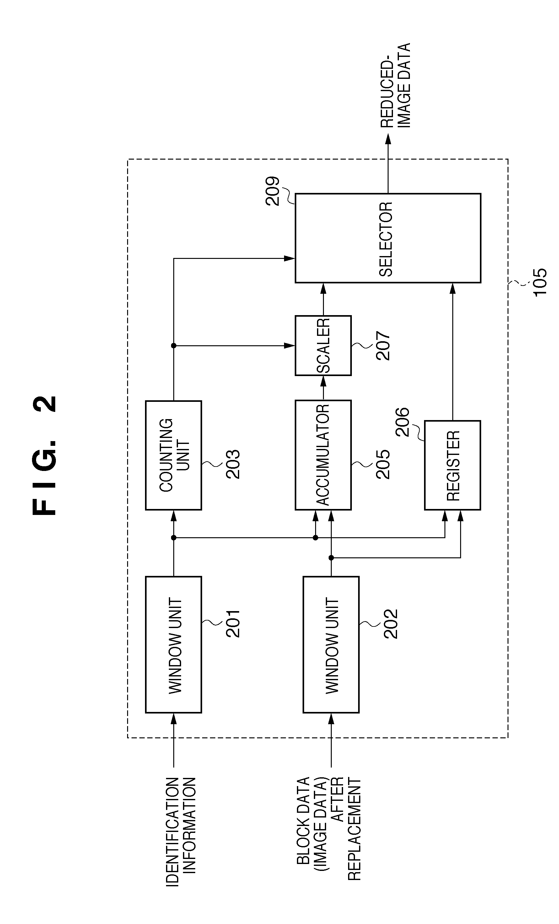
[0079]In a case where all pixels within the window of size 2×2 pixels are pixels having a replacement color, the selector 209 (see FIG. 2) of the first embodiment outputs this replacement color as the pixel value of one pixel after execution of reduction processing. Accordingly, if a pixel of a non-extracted color and a pixel indicated by a replacement color are mixed with the 8×8 pixels obtained by reduction processing, there is a possibility that the value of the non-extracted-color pixel will be influenced by the extracted color owing to the DCT and quantization of JPEG encoding.

[0080]Accordingly, in a second embodiment of the invention, an example in which this point is further improved upon will be described.

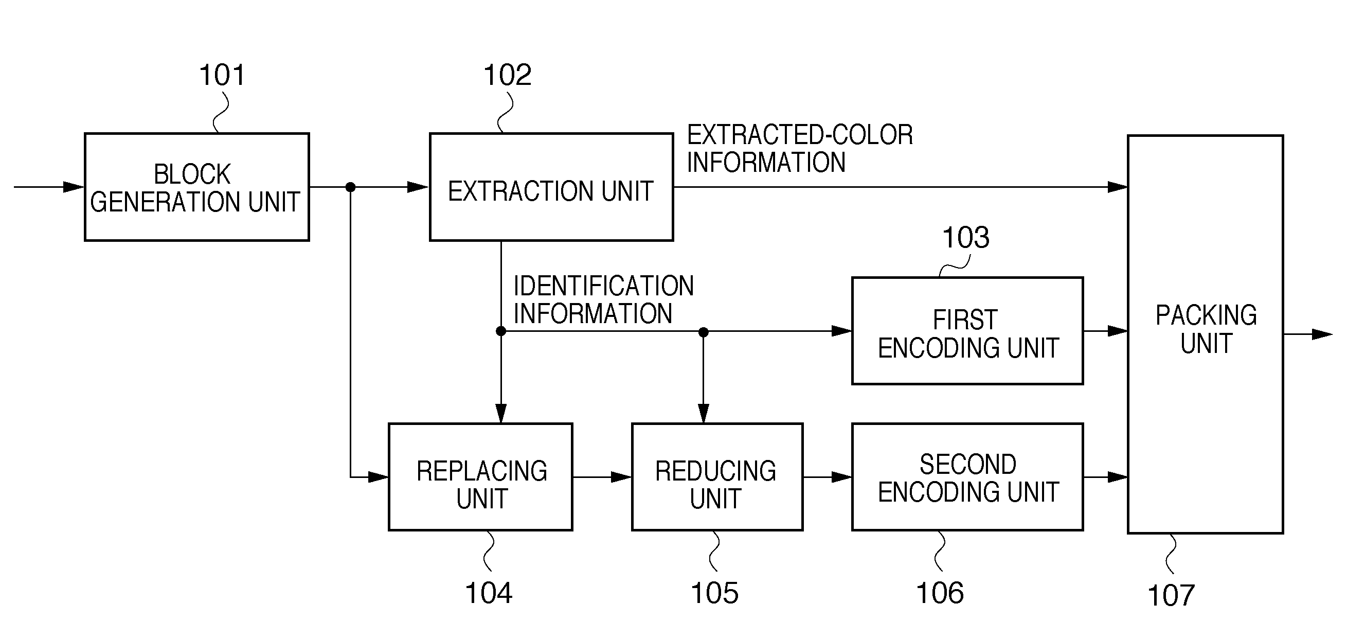
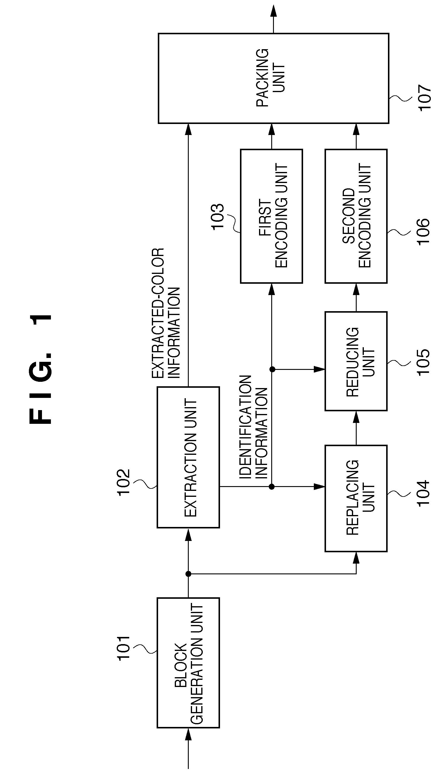
[0081]The configuration of the image encoding apparatus according to the second embodiment is the same as that shown in FIG. 1; what differs is the configuration of the reducing unit 105.

[0082]FIG. 5 is a block diagram of the reducing unit 105 according to the second embodi...

third embodiment

[0090]The processing executed by the replacing unit 210 of the second embodiment may be adapted as set forth below.

[0091]When the pixel of interest is a replacement color, it is replaced with the average value of neighboring pixel values for which the count value is “1” or greater. In the case of FIG. 6, if it is assumed that the pixel value after replacement of the pixel of interest will be P5′, then P5′ is calculated according to the following equation:

P5′=(P1+P2+P3+P4+P7+P8+P9) / 7

Actions and effects similar to those of the second embodiment can be obtained with the third embodiment as well.


PUM


Abstract

This invention encodes an image mixed of a character or line-drawing image and a natural image. An extraction unit extracts the color of a pixel, which constitutes a high-frequency component, from the input image data as an extracted color and generates identification information indicating whether each pixel in the image data is a pixel of an extracted color or non-extracted color. A replacement unit replaces a pixel value of an extracted color with an average value of non-extracted colors. Using a window having a size of 2×2 pixels, a reducing unit generates one pixel from the window after replacement. If even one non-extracted-color pixel exists in the window, the average value of non-extracted colors within the window is determined to be a pixel value of the reduced image. A packing unit concatenates the extracted color, the result of lossless-encoded identification information and lossy-encoded data of the reduced image.

Description

BACKGROUND OF THE INVENTION[0001]1. Field of the Invention[0002]The present invention relates to a technique for encoding image data.[0003]2. Description of the Related Art[0004]The following encoding method is available as a technique for compressing a multi-valued image that is a mixture of characters or line drawings and natural images: Inputting an image in block units from an input multi-valued image; extracting identification information indicating whether a pixel is a character or line-drawing image having a color or density designated in advance; applying entropy encoding to the extracted identification information; and, on the other hand, encoding a multi-valued image that is not a character or line drawing by using an orthogonal transform or the like.[0005]Japanese Patent Application Laid-Open No. 04-326669 can be mentioned as one example of a reference that discloses such a technique. According to this reference, an input image is divided into blocks serving as units of o...

Claims


Application Information

Patent Timeline
Patent Type & Authority Patents(United States)
IPC IPC(8): G06K9/46H04N1/41H04N1/413H04N19/00H04N19/102H04N19/136H04N19/14H04N19/167H04N19/176H04N19/196H04N19/59H04N19/625H04N19/91
CPCH04N1/642
Inventor TSUTSUMI, TAKAYUKIISHIKAWA, HISASHI
Owner CANON KK
Why Eureka
Try Eureka