Floor construction method and system

a construction method and floor technology, applied in the field of floor construction methods and systems, can solve the problems of difficult to use standard h-sections, difficult to meet the requirements of construction, and significant drawbacks of each section, and achieve the effect of reducing the weight of the next strongest section, reducing the difficulty of using standard h-sections, and improving the quality of construction

Active Publication Date: 2011-10-04
ASD WESTOK
View PDF38 Cites 14 Cited by
  • Summary
  • Abstract
  • Description
  • Claims
  • Application Information

AI Technical Summary

Benefits of technology

[0015]The present invention provides a floor construction method and system that enables the construction of robust flooring and which enables various service structures to be located within the floor structure. The present invention also provides a structural beam with openings in the web and a method of producing such a structural beam, the structural beam being suitable for use in the floor construction method and system of the present invention.

Problems solved by technology

For shallow floor construction it is very difficult to use standard H-section because the concrete flooring unit cannot be safely lowered into place without fouling the projection of the top flange of the H-section.
Several forms of asymmetric shallow steel beams are known, but each has significant drawbacks.
However, these beams have several drawbacks:a) There is a very limited range of section sizes, consisting of 10 depths in increments between 272 mm to 342 mm;b) The shallowest, 272 mm deep, is too deep for many ultra-shallow floors;c) In order to achieve composite action sufficient cover of concrete and reinforcement must be placed over the Slimdek top flange, further increasing depth;d) Due to the small number of beams in the range, the weight increase from one to the next strongest is very substantial, making for unnecessarily heavy construction.
This has the benefit of providing a greater range of beam depths, but is still restricted by the limited range of H-beams available in any market.
However, most commercially available automated welding systems cannot gain access to weld a beam less than 300 mm in depth.
Moreover, unless the welds that join the vertical and horizontal plates are full strength butt welds, which are prohibitively expensive, a plate H-beam is significantly inferior to rolled section in its load carrying capacity.
Each of the above types of steel beam have another important practical drawback.

Method used


Image

  • Floor construction method and system
  • Floor construction method and system
  • Floor construction method and system

Examples


Embodiment Construction

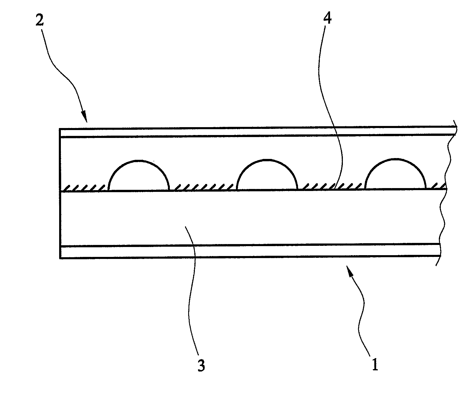
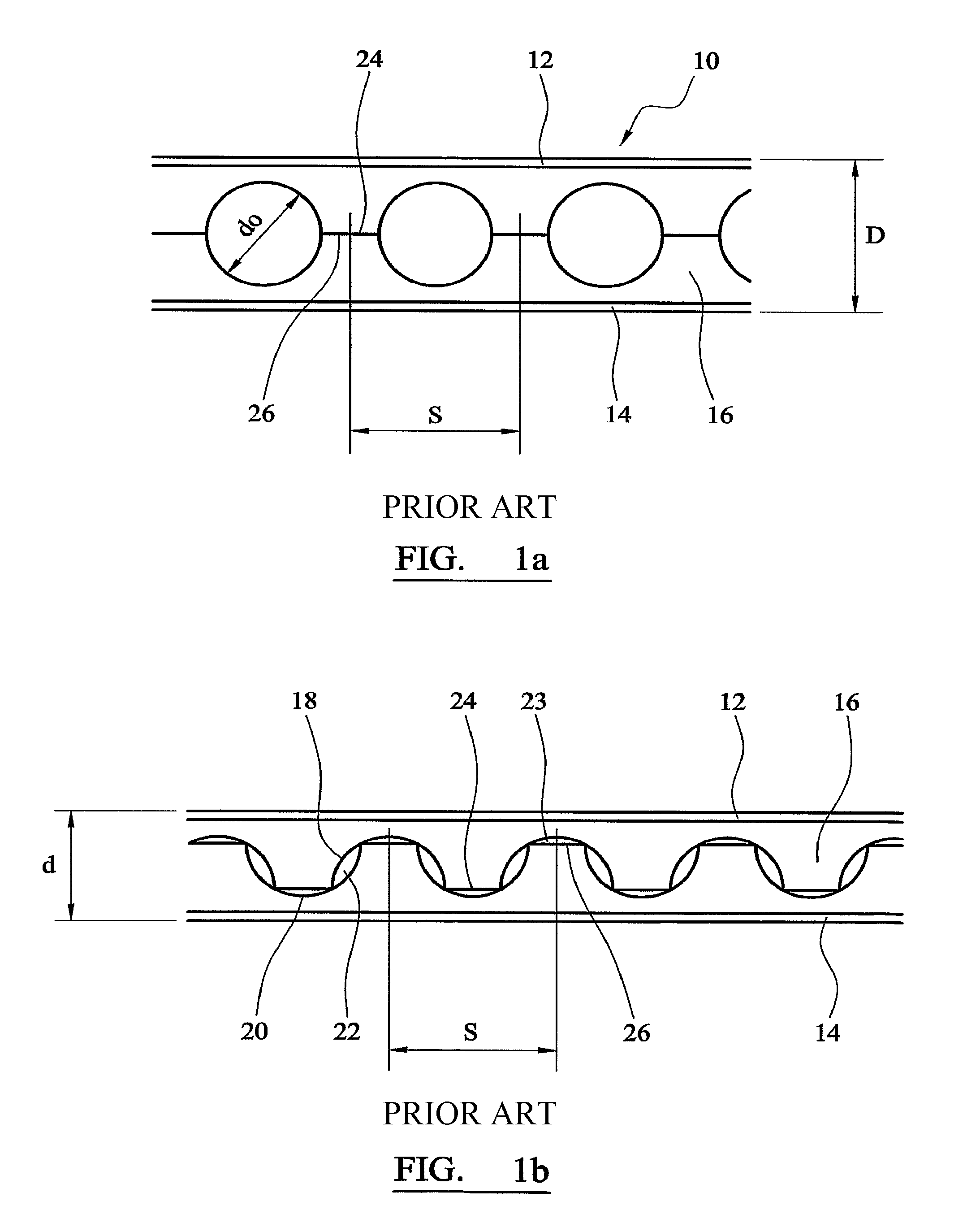
[0057]The present invention utilises structural beams with openings in the webs, referred to as “cellular beams”. Cellular beams are well known in the art, and those produced according to the method of EP 0324206 are particularly suitable. FIGS. 1a and 1b correspond to FIGS. 1a and 1b in EP 0324206 and illustrate a finished cellular beam and cut pattern, respectively.

[0058]The method according to EP 0324206 comprises the steps of taking a universal beam, making a cut generally longitudinally along the web thereof, separating the cut halves of the beam, displacing the halves with respect to one another and welding the halves together, characterised in that: a second cut is made along the web, the path differing from the first path of the first cut, the two paths being defined by rectilinear sections lying on alternative sides of a longitudinal centre line of the web and at least partly curvilinear sections joining the closest ends of adjacent rectilinear sections.

[0059]As shown in FI...


PUM

PropertyMeasurementUnit
depthsaaaaaaaaaa
sizesaaaaaaaaaa
sizesaaaaaaaaaa

Abstract

This invention relates to a floor construction method and system, and more particularly to a method for producing shallow and ultra shallow steel floor systems.

Description

BACKGROUND OF THE INVENTION[0001]This invention relates to a floor construction method and system, and more particularly to a method for producing shallow and ultra shallow steel floor systems. Ultra-shallow steel floor systems may be defined as those having depths in the range 100 mm to 350 mm.[0002]In multi-storey buildings it has become increasingly important to minimise the overall floor-to-floor height, and consequently the depth taken up by any floor structure needs to be minimised. This need is driven by increased levels of servicing accommodated within modern ceiling and floor zones, and the desire to accommodate as many floors as possible, without contravening planning restrictions on the allowable overall building height. Historically, very compact construction was achieved by using thin structural concrete slab with closely spaced columns.[0003]In recent years engineers have sought methods to construct equally compact floors in steel rather than concrete. This invention i...

Claims


Application Information

Patent Timeline
Patent Type & Authority Patents(United States)
IPC IPC(8): E04B1/20E04B5/29E04B5/40E04C3/08E04C3/293
CPCE04B5/29E04B5/40E04C3/291E04C3/293E04C3/086Y10T29/49634
Inventor HOLMES, ANDREWHAWES, MICHAEL
Owner ASD WESTOK
Why Eureka
Try Eureka