Actuator for vibrating a sound board in a musical instrument and method for attaching same

a technology of sound board and actuator, which is applied in the direction of transducer diaphragm, instruments, transducer details, etc., can solve the problems of complicated operation, cumbersome and cumbersome adjustment operation, and limited frequency at which good responsiveness can be obtained, so as to achieve the effect of increasing

Active Publication Date: 2015-05-14
YAMAHA CORP
View PDF9 Cites 7 Cited by
  • Summary
  • Abstract
  • Description
  • Claims
  • Application Information

AI Technical Summary

Benefits of technology

[0006]It is therefore an object of the present invention to provide a voice coil type actuator which can be attached to the sound board with ease. It is another object of the present invention to provide a voice coil type actuator which can be attached to the sound board in such a manner that the voice coil is positioned at a desired ideal position within a magnetic path space of the voice coil.
[0009]According to the present invention arranged in the aforementioned manner, the end member connected to the bobbin connects the bobbin indirectly to the sound board of the musical instrument so as to transmit vibration of the bobbin (voice coil) to the sound board. The connection member is constructed to be adjustable in length, and thus, when the actuator is to be attached to the sound board, the connection member of the actuator can be connected to the sound board by mere adjustment of the length of the connection member without the magnetic path formation section and the bobbin (voice coil) being moved in position. In this way, the actuator can be attached to the sound board with an increased ease. Further, because the connection member can be connected to the sound board, by mere adjustment of the length of the connection member, with relative positional relationship between the magnetic path formation section and the bobbin (bobbin coil) maintained in a predetermined reference mounting position. Thus, according to the present invention, operations for attaching the actuator to the sound board with relative positional relationship between the magnetic path formation section and the bobbin (bobbin coil) maintained in the reference mounting position can be performed with an increased ease.
[0014]Further, by incorporating the aforementioned actuator attaching method into the aforementioned musical instrument manufacturing method, the present invention can provide a novel and useful musical instrument manufacturing method.
[0016]In this actuator, the through-hole portion is formed in the portion of the magnetic path formation section inserted in the inner space of the bobbin, and the mark designating a position at which the fixation member is to be fastened is provided on the portion of the end member opposed to the through-hole portion. By the provision of such a mark, the operation for connecting the connection member to the sound board by means of the fixation member can be performed with an increased ease. Further, because the through-hole portion is formed in the portion of the magnetic path formation section inserted in the inner space of the bobbin, a tool (e.g., screwdriver) to be used in the operation for connecting the end member to the sound board by means of the fixation member (e.g., screw) can be readily introduced through the through-hole portion to a predetermined connection point. In this way, the present invention can provide a construction that effectively facilitates the operations for attaching the actuator to the sound board. Further, because, with the bobbin (voice coil) disposed within the magnetic path formation section, the fixation member (e.g., screw) can be readily introduced through the through-hole portion to the predetermined connection point so that the connection member fixing operation is performed. Thus, it is possible to eliminate a need for employing an operational sequence of first connecting the bobbin (voice coil) to the sound board and combining the magnetic path formation section to the bobbin (voice coil) as done in the prior art technique. As a result, the operations for attaching the actuator to the sound board can be performed in such a manner that the bobbin and the magnetic path formation section do no contact each other.
[0017]According to still another aspect, the present invention provides a method for attaching the aforementioned actuator to a musical instrument, which comprises: a step of providing a support section in association with an actuator-attaching position of the sound board to which the actuator is to be attached and installing the magnetic path formation section on the support section; a step of introducing, through the through-hole portion of the magnetic formation section, the fixation member to a position of the mark of the end member; and a step of fixing the end member to the sound board by means of the fixation member introduced to the position of the mark. Further, by incorporating the aforementioned actuator attaching method into the aforementioned musical instrument manufacturing method, the present invention can provide a novel and useful musical instrument manufacturing method.
[0019]According to that aspect, when the actuator is to be attached to the sound board, the support section and the actuator can be moved as a unit to a position where the connection member of the actuator is to be connected to the sound board, by mere adjustment of the relative distance of the support section to the sound board, without the magnetic path formation section and the bobbin (voice coil) being moved in position within the actuator. In this way, the actuator can be attached to the sound board with an increased ease. Further, because the connection member can be connected to the sound board by mere adjustment of the support section with relative positional relationship between the magnetic path formation section and the bobbin (bobbin coil) maintained in the predetermined reference mounting position, the operations for attaching the actuator to the sound board with the relative positional relationship between the magnetic path formation section and the bobbin (bobbin coil) maintained in the reference mounting position can be performed with an increased ease.

Problems solved by technology

But, as such a dimension, in the vibrating direction, of the voice coil increases, inductance increases, so that frequencies at which good responsiveness can be obtained would be limited to low frequencies.
In such a case, there is a need to finely adjust a position, in the vibrating direction, of the bobbin in order to mount the bobbin and the yoke at their respective accurate position, and such an adjusting operation tends to be cumbersome and complicated.
In such a case, however, cumbersome and complicated operations would be required because the human operator has to perform the operations for fixing the magnet and the yokes while finely adjusting the positions of the yokes in various directions in such a manner that the bobbin and the yokes do not contact each other.

Method used


Image

  • Actuator for vibrating a sound board in a musical instrument and method for attaching same
  • Actuator for vibrating a sound board in a musical instrument and method for attaching same
  • Actuator for vibrating a sound board in a musical instrument and method for attaching same

Examples


first embodiment

of the Vibration Device

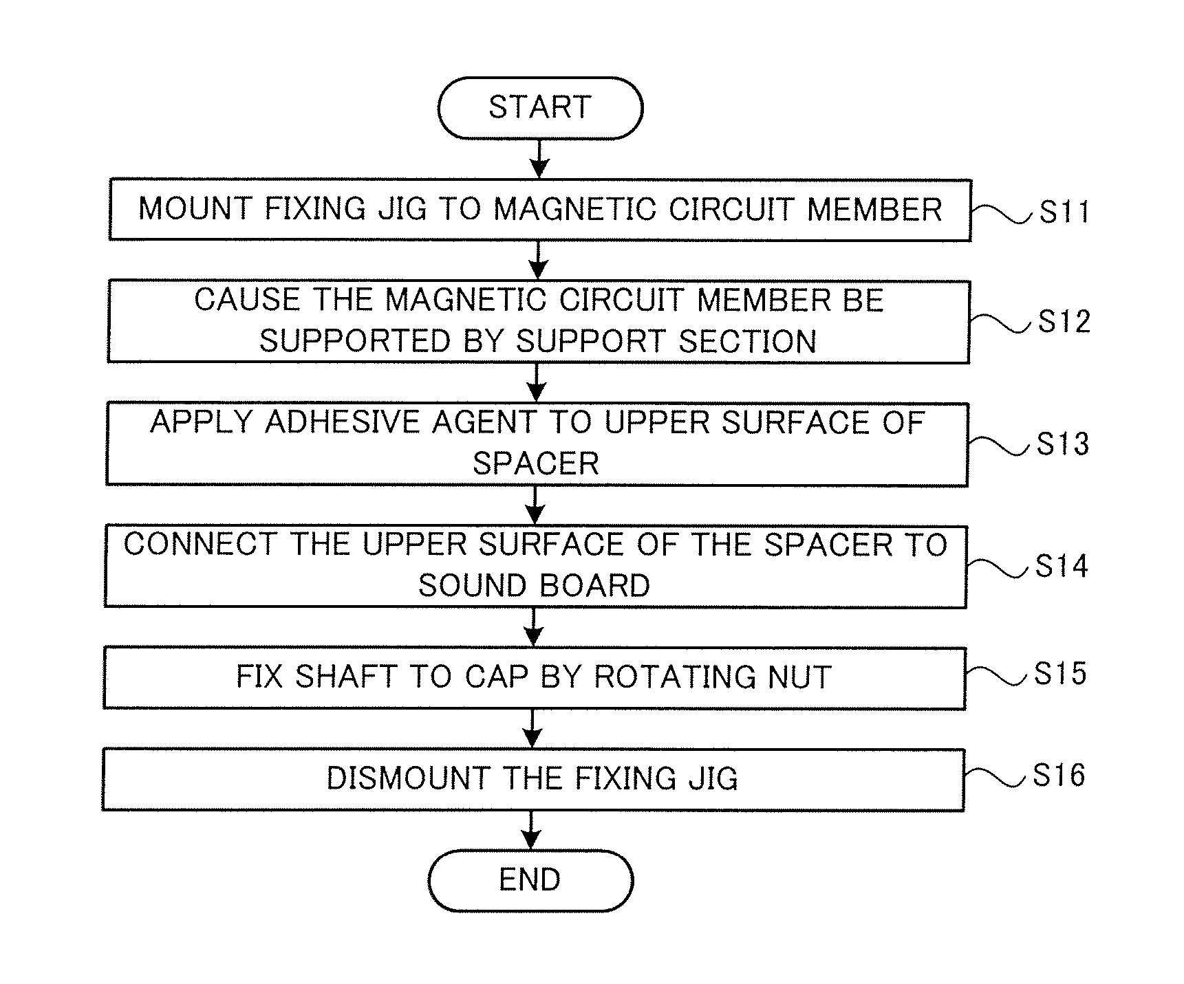
[0074]FIG. 4 is a view showing an outer appearance of a first embodiment of the vibration device 50 of the present invention. The vibration device 50 includes the vibration member 51, the magnetic circuit member 52 and a damper 53. The vibration member 51 includes: a voice coil 513 attached to a bobbin 511; a cap 512 connected to a distal end portion of the bobbin 511; a shaft 514; and a spacer 516. The cap 512 is a disk-shaped member. The shaft 514 is a rod-shaped member and has one longitudinal end portion fixed to the center of the circular surface of the cap 512, and the spacer 516 is mounted on another longitudinal end portion of the shaft 514. The spacer 516 is a member of a circular columnar shape and has a flat end surface opposite from its end portion mounted on the shaft 514. The flat end surface, which has a circular shape having a diameter φ, is a surface to be connected to the sound board 7. In the following description, a direction along a normal...

second embodiment

of the Vibration Device

[0142]FIG. 22 is a view showing an outer appearance of a second embodiment of the vibration device 50A of the present invention. The second embodiment of the vibration device 50A does not include the mounting shaft 514 as employed in the first embodiment of the vibration device 50. Although the second embodiment of the vibration device 50A is different from the first embodiment of the vibration device 50 in terms of the structure by which the vibration device 50A is attached to the sound board 7, it may be similar to the first embodiment of the vibration device 50 in terms of the other structures by which it performs its primary function as a vibration device. Thus, in the following description and drawings pertaining to the second embodiment, similar elements to the first embodiment are indicated by the same reference numerals as used in the first embodiment and will not be described here to avoid unnecessary duplication.

[0143]According to the second embodime...

third embodiment

of the Vibration Device

[0179]FIG. 35 is a vertical sectional view of a third embodiment of the vibration device 50C. The third embodiment of the vibration device 50C has a mounting-length-adjustable connecting shaft 514A for mounting the connection member 51 to the sound board 7, which is different in construction from the shaft 514 provided in the first embodiment of the vibration device 50. The construction of the third embodiment of the vibration device 50C for performing its primary function as a vibration device may be similar to that of the first or second embodiment of the vibration device 50 or 50A. Thus, in the following description and drawings pertaining to the third embodiment, similar elements to the first or second embodiment are indicated by the same reference numerals as used in the first or second embodiment and will not be described here to avoid unnecessary duplication.

[0180]In FIG. 35, a housing formed of non-magnetic material (aluminum, synthetic resin or the li...


PUM

PropertyMeasurementUnit
temperatureaaaaaaaaaa
magneticaaaaaaaaaa
lengthaaaaaaaaaa

Abstract

In an actuator (50), a bobbin (511) to which a voice coil (513) is attached is disposed within a magnetic path space formed by a magnetic path forming section (52). A connecting shaft (514) is coupled to the bobbin (511), and a connection end portion (516A) at a distal end of the connecting shaft is connected to a sound board of a musical instrument. The length of the shaft (514) can be adjusted. When the actuator (50) is attached to the sound board, the length of the shaft (514) is adjusted and the connection end portion (516A) is connected to the sound board while a position of the voice coil (513) within the magnetic path space is maintained in a predetermined reference mounting position, in a state in which the magnetic path forming unit (52) is supported in a predetermined position by a support unit (55).

Description

TECHNICAL FIELD[0001]The present invention relates to a voice coil type actuator for positively imparting vibration to a sound board of a musical instrument and a method for attaching the actuator to the musical instrument, as well as a musical instrument provided with the actuator and a method for manufacturing the same.BACKGROUND ART[0002]In electronic pianos, electronic tones (sounds) are audibly generated or sounded through an electromagnetic speaker. In some of the electronic pianos too, a sound board is provided to generate not only electronic tones but also natural spreading of tones and rich low-pitched tones. Patent Literature 1 discloses a technique in accordance with which an electromagnetic speaker is mounted on the sound board to vibrate the sound board with the electromagnetic speaker so that a tone is radiated from the sound board.PRIOR ART LITERATURE[0003]Patent Literature 1: Japanese Translation of PCT International Application No. HEI-4-500735[0004]To vibrate the s...

Claims


Application Information

Patent Timeline
Patent Type & Authority Applications(United States)
IPC IPC(8): G10H1/32H04R31/00
CPCH04R31/00G10H1/32G10H3/22G10H2220/501G10H2220/505H04R1/028H04R7/045H04R9/02H04R9/04H04R11/02H04R31/006H04R2209/024H04R2440/05H04R2440/07Y10T29/49005
Inventor OHNISHI, KENTATAKAHASHI, YUJI
Owner YAMAHA CORP
Why Eureka
Try Eureka