Cartridge for applying varying amounts of tissue compression

a tissue compression and cartridge technology, applied in the field of cartridges for applying varying amounts of tissue compression, can solve the problems of needless reduction of blood flow to the tissue surrounding the cut-line, decreased hemostasis time, and elevated necrosis level, so as to the degree of hemostasis, and improve the anastomotic strength. effect of degree of hemostasis

Active Publication Date: 2011-10-04
COVIDIEN LP
View PDF116 Cites 1515 Cited by
  • Summary
  • Abstract
  • Description
  • Claims
  • Application Information

AI Technical Summary

Benefits of technology

[0012]The present disclosure is directed towards surgical stapling instruments configured to effectuate an improved balance between the anastomotic strength and the degree of hemostasis at the tissue interface. In particular, embodiments of the present disclosure include surgical fasteners of different sizes. Further still, the distance between an anvil member and a staple cartridge (i.e. the gap) varies along a longitudinal axis of the staple cartridge. Combining the different sizes of surgical fasteners with the varying gap between the anvil member and the staple cartridge improves the anastomotic strength and the degree of hemostasis at the tissue interface.

Problems solved by technology

It is commonly known that by increasing the amount of pressure applied to a wound, the flow of blood can be limited, thereby decreasing the time necessary to achieve hemostasis.
Each of the fasteners will generally apply a compressive force to the tissue sufficient to effectuate hemostasis, however, if too much pressure is applied, this can result in a needless reduction in blood flow to the tissue surrounding the cut-line.
Accordingly, the joining of tissue together in this manner may result in an elevated level of necrosis, a slower rate of healing, and / or a greater recovery period.

Method used


Image

  • Cartridge for applying varying amounts of tissue compression
  • Cartridge for applying varying amounts of tissue compression
  • Cartridge for applying varying amounts of tissue compression

Examples


Embodiment Construction

[0025]Embodiments of the presently disclosed surgical stapling instruments will now be described in detail with reference to the drawing figures wherein like reference numerals identify similar or identical elements. In the drawings and in the description which follows, the term “proximal”, as is traditional, will refer to the end of the surgical stapling instrument which is closest to the operator while the term “distal” will refer to the end of the device which is furthest from the operator.

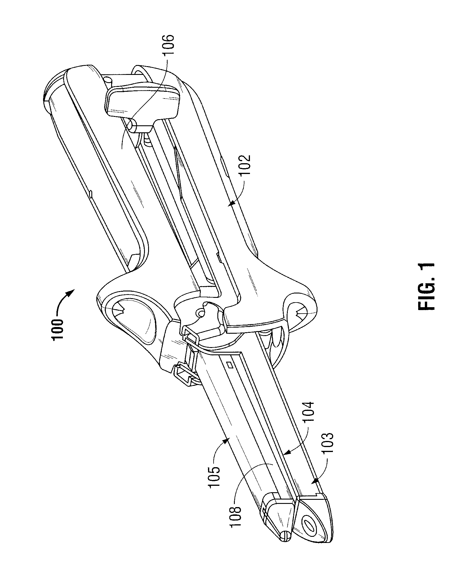
[0026]Turning now to FIG. 1, a surgical stapling instrument, of the gastrointestinal anastomosis type for performing surgical anastomotic stapling, in accordance with an embodiment of the disclosure, is generally designated as 100. Surgical stapling instrument 100 includes a first handle 102 having a jaw 103 defining a staple cartridge receiving section extending from a distal end thereof, a staple cartridge 104 receivable in jaw 103, a second handle 106 having a jaw 105 defining an anvil membe...


PUM

PropertyMeasurementUnit
lengthaaaaaaaaaa
lengthaaaaaaaaaa
lengthaaaaaaaaaa

Abstract

A surgical stapling apparatus includes a staple cartridge and an anvil member. The staple cartridge includes a plurality of surgical fasteners disposed in rows of retention slots. The staple cartridge may have an annular or linear configuration of retention slots. The tissue contacting surface of the staple cartridge may be tapered or stepped. The anvil member has a tissue contacting surface that includes a number of pockets arranged for substantially aligning with the retention slots. In addition, the tissue contacting surface of the anvil member may complement the tissue contacting surface of the staple cartridge.

Description

CROSS REFERENCE TO RELATED APPLICATION[0001]This application claims priority to, and the benefit of, U.S. Provisional Patent Application Ser. No. 61 / 046,883 filed on Apr. 22, 2008, the contents of which are hereby incorporated by reference in their entirety.BACKGROUND[0002]1. Technical Field[0003]The present disclosure relates to surgical fastener apparatus and surgical fastener cartridges, and more particularly, to apparatus and cartridges for applying varying amounts of tissue compression.[0004]2. Background of Related Art[0005]Many varieties of surgical fastening apparatus are known in the art, some of which are specifically adapted for use in various surgical procedures including, but not limited to, end-to-end anastomosis, circular end-to-end anastomosis, open gastrointestinal anastomosis, endoscopic gastrointestinal anastomosis, and transverse anastomosis. Suitable examples of apparatus which may be used during the course these procedures can be seen in U.S. Pat. Nos. 5,915,61...

Claims


Application Information

Patent Timeline
Patent Type & Authority Patents(United States)
IPC IPC(8): A61B17/068
CPCA61B17/064A61B17/0686A61B17/068A61B17/07207A61B2017/07235A61B2017/07242A61B17/115A61B2017/07214A61B17/105
Inventor SNIFFIN, KEVINSOLTZ, MICHAEL
Owner COVIDIEN LP
Why Eureka
Try Eureka