Retrievable filter

Active Publication Date: 2011-10-04
CR BARD INC
View PDF57 Cites 83 Cited by
  • Summary
  • Abstract
  • Description
  • Claims
  • Application Information

AI Technical Summary

Benefits of technology

[0012]In one embodiment, a blood vessel filter includes a first set of struts joined together at a joined end, the struts extending radially outward therefrom in a first direction, at least one of the first set of struts including a hook on a free end, the hook having a cross-sectional area less than a cross-sectional area of the strut, a sec

Problems solved by technology

When the thrombus clot loosens from the site of formation and travels to the lung, it may cause pulmonary embolism, a life-threatening condition.
Many of the existing vena cava filters routinely encounter problems during retrieval.

Method used


Image

  • Retrievable filter
  • Retrievable filter
  • Retrievable filter

Examples


Embodiment Construction

in conjunction with the accompanying drawings that are first briefly described.

BRIEF DESCRIPTION OF THE DRAWINGS

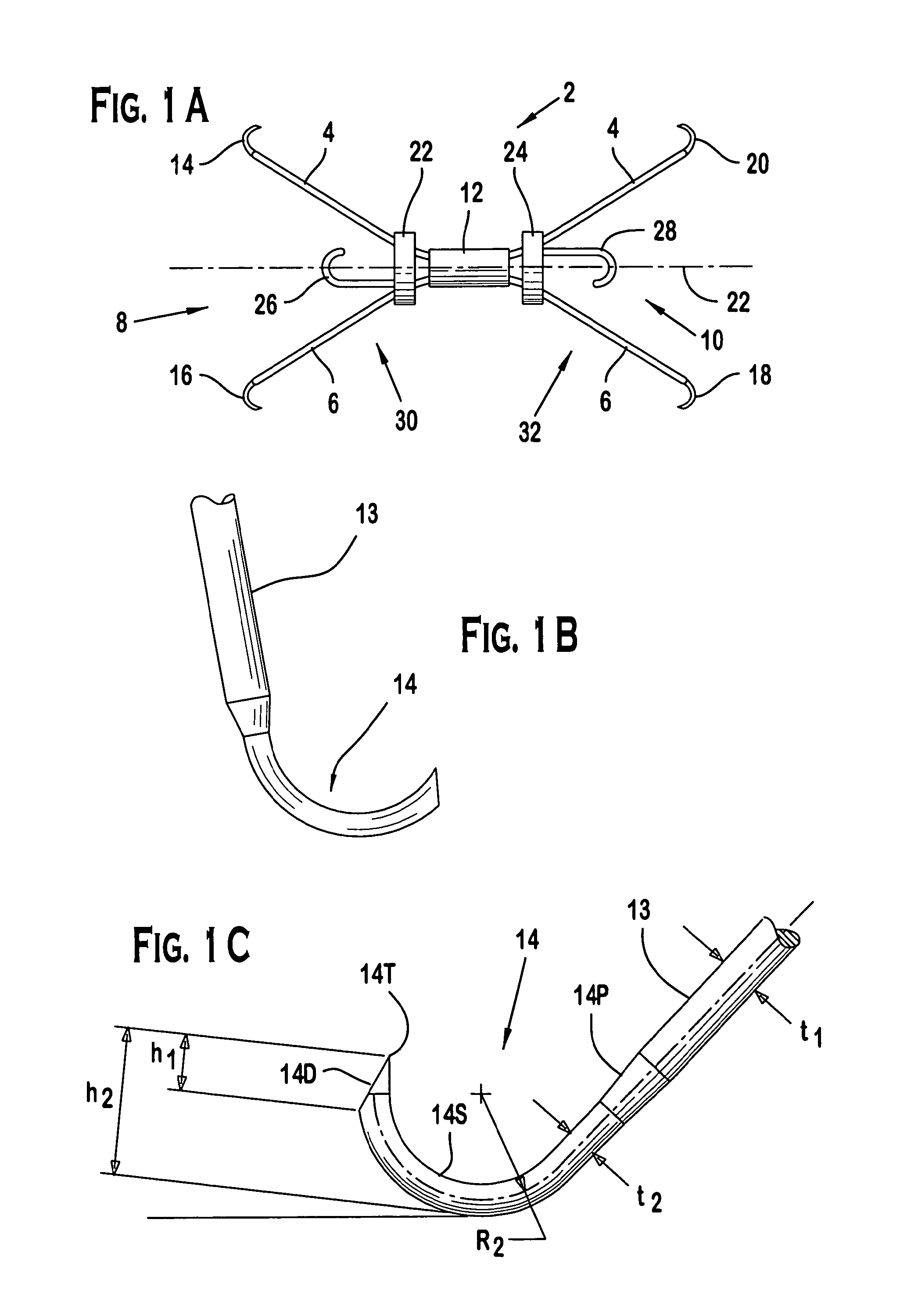
[0014]FIG. 1A illustrates one variation of a vessel filter with an integrated compression mechanism for filter recovery. The filter includes struts forming two cones at the distal and the proximal ends of the filter. Two slidable members are displaced over the struts to serve as the compression mechanism.

[0015]FIG. 1B is a side view of one embodiment of a hook for the vessel filter of FIG. 1A.

[0016]FIG. 1C is a side view of another embodiment of a hook for the vessel filter of FIG. 1A.

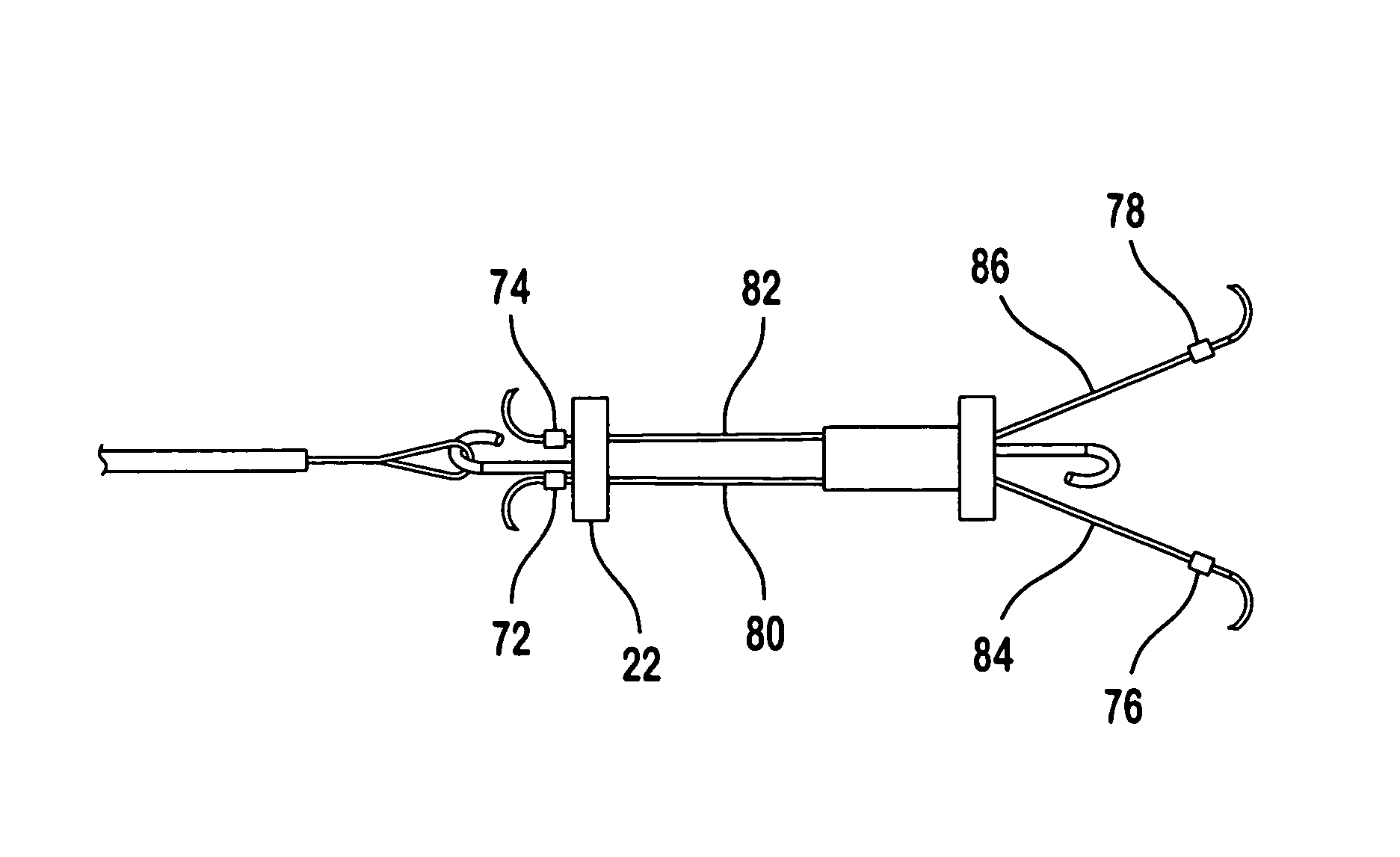
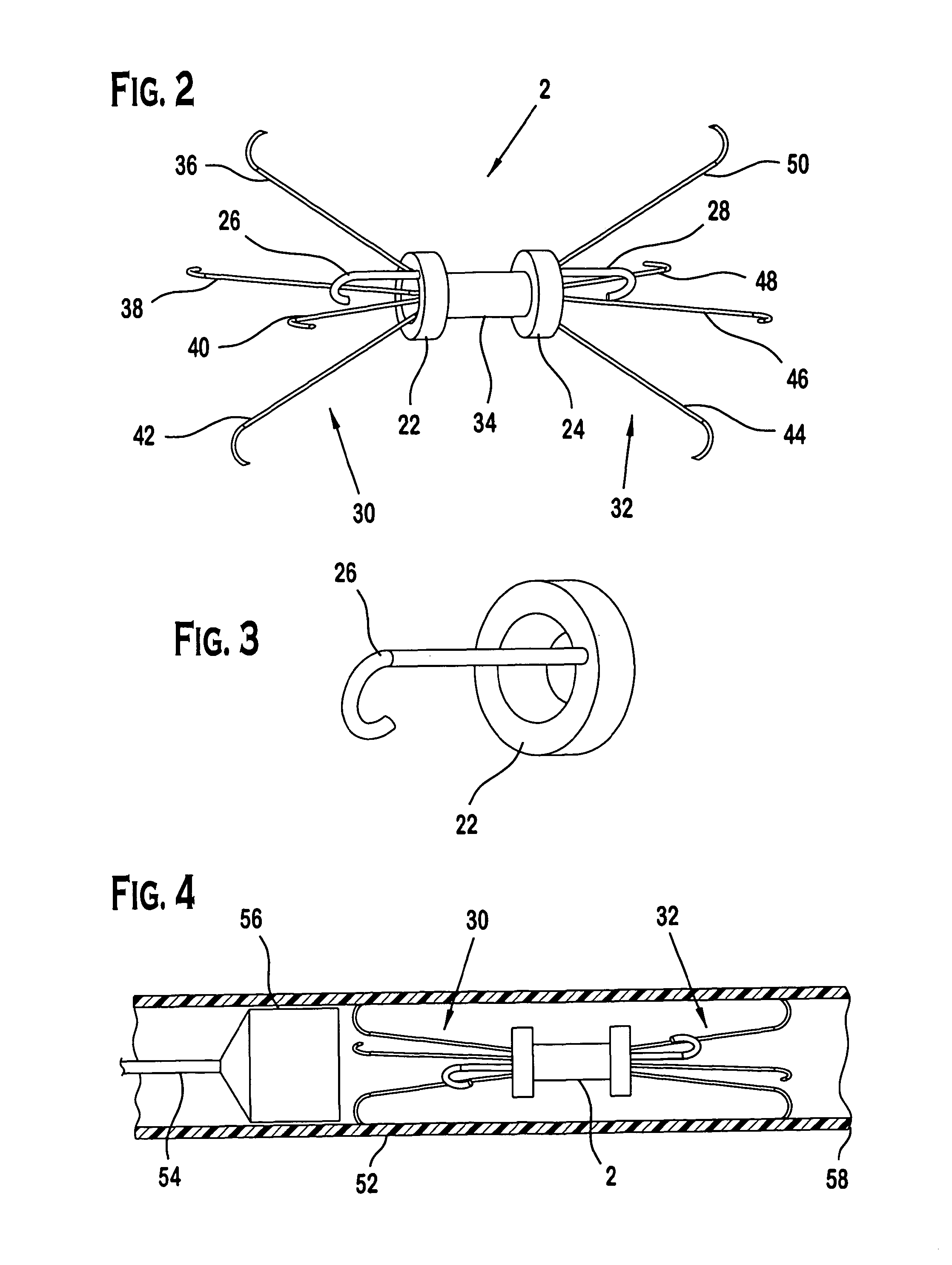
[0017]FIG. 2 is a perspective view of another variation of the vessel filter comprising a connecting member supporting a first set of flexible wiring extending radially from the proximal end of the connecting member, and a second set of flexible wiring extending radially from the distal end of the connecting member. Two slidable members are disposed over the length of the vessel filter for co...


PUM


Abstract

A vessel filter including a plurality of struts forming a first collapsible cone expanding radially outward in a proximal direction and a second collapsible cone expanding radially outward in a distal direction. A slidable member is disposed over the plurality of struts to collapse the struts toward a longitudinal axis of the vessel filter.

Description

RELATED APPLICATIONS[0001]This application is a divisional of U.S. patent application Ser. No. 11 / 334,829, filed Jan. 19, 2006, now abandoned, which claims the benefit of U.S. Provisional Patent Application No. 60 / 645,347, filed Jan. 19, 2005, each of which is incorporated by reference in its entirety herein.BACKGROUND OF THE INVENTION[0002]A vessel filter is a device inserted into a blood vessel to capture particles in the blood flow. Typically the device is inserted into a major vein to prevent a blood clot from reaching the lungs. Patients, who have recently suffered from trauma, have experienced a heart attack (myocardial infarction), or who have undergone major surgical procedure (e.g., surgical repair of a fractured hip, etc.) may have thrombosis in a deep vein. When the thrombus clot loosens from the site of formation and travels to the lung, it may cause pulmonary embolism, a life-threatening condition. A vessel filter may be placed in the circulatory system to intercept the...

Claims


Application Information

Patent Timeline
IPC IPC(8): A61M29/00
CPCA61F2/01A61F2002/016A61F2230/005A61F2230/0058A61F2230/0078A61F2/012
Inventor CHANDUSZKO, ANDRZEJ J.
Owner CR BARD INC
Why Eureka
Try Eureka