
Safety device for exercise resistance bands

a safety device and resistance band technology, applied in the field of exercise devices, can solve the problems of reducing the possibility of mounting to mar the mounting surface, and achieve the effects of reducing the risk of snapback or recoil injury, improving the surface area of the center portion, and improving the safety. and comfor

Inactive Publication Date: 2011-10-11
AYOUB VICTOR R
View PDF58 Cites 40 Cited by
  • Summary
  • Abstract
  • Description
  • Claims
  • Application Information

AI Technical Summary

Benefits of technology

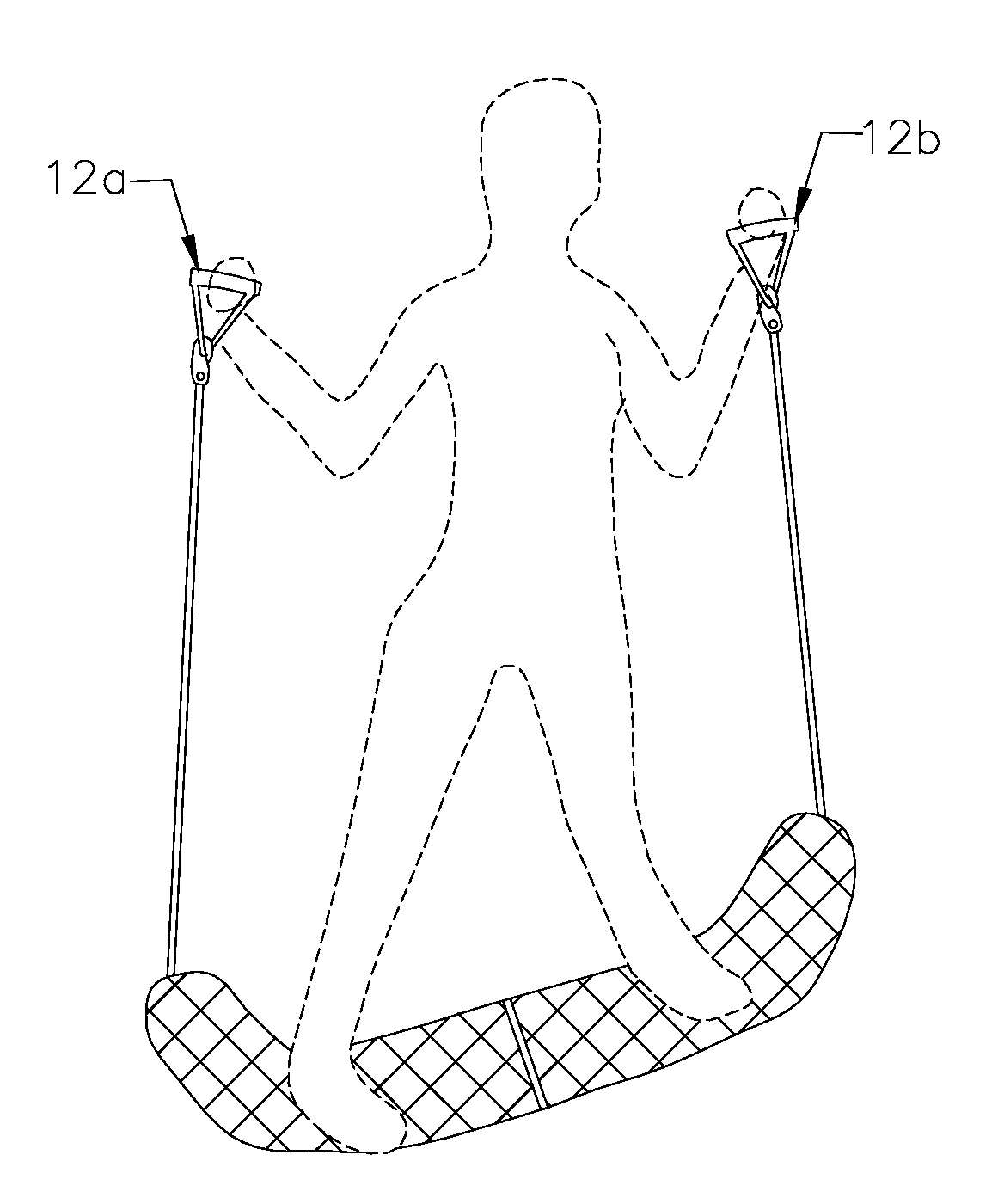
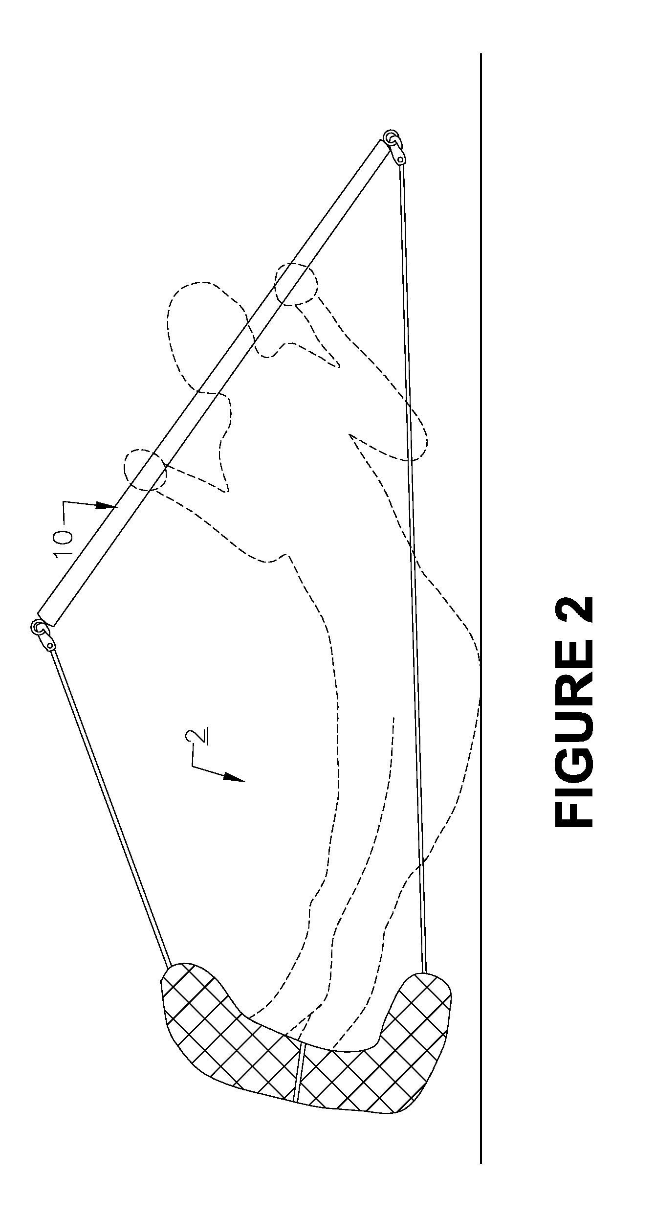
The new fail-safe design for the exercise band greatly lowers the risk of snap back or recoil injury to a user of an exercise device which includes an elastic exercise resistance band. In the present invention, an element is added to the band upon which element a resistance effect of wind or air can act, so as to form a type of parachute or air brake which will slow or stop the snap back effect of the resistance band in the event of a failure or unwanted release of the band from a mount.
Furthermore, the new design for the exercise resistance band eliminates the need for a separate component to mount the exercise band to a door and also the method by which the design for the exercise band does mount to a door greatly lowers the risk of band snap. Additionally, the mounting techniques possible with the new design, greatly reduces the possibility of the mounting to mar the mounting surface, such as a door frame, as commonly occurs with door mounts for the currently used resistance band exercise devices.
Because of the reduced potential for injury provided by the improved design, users of exercise devices having a resistance band of this new type, in general will feel more confident to use exercise devices, and thus help ensure the completion of regularly scheduled exercise,

Problems solved by technology

Additionally, the mounting techniques possible with the new design, greatly reduces the possibility of the mounting to mar the mounting surface, such as a door frame, as commonly occurs with door mounts for the currently used resistance band exercise devices.

Method used


Image

  • Safety device for exercise resistance bands
  • Safety device for exercise resistance bands
  • Safety device for exercise resistance bands

Examples


Embodiment Construction

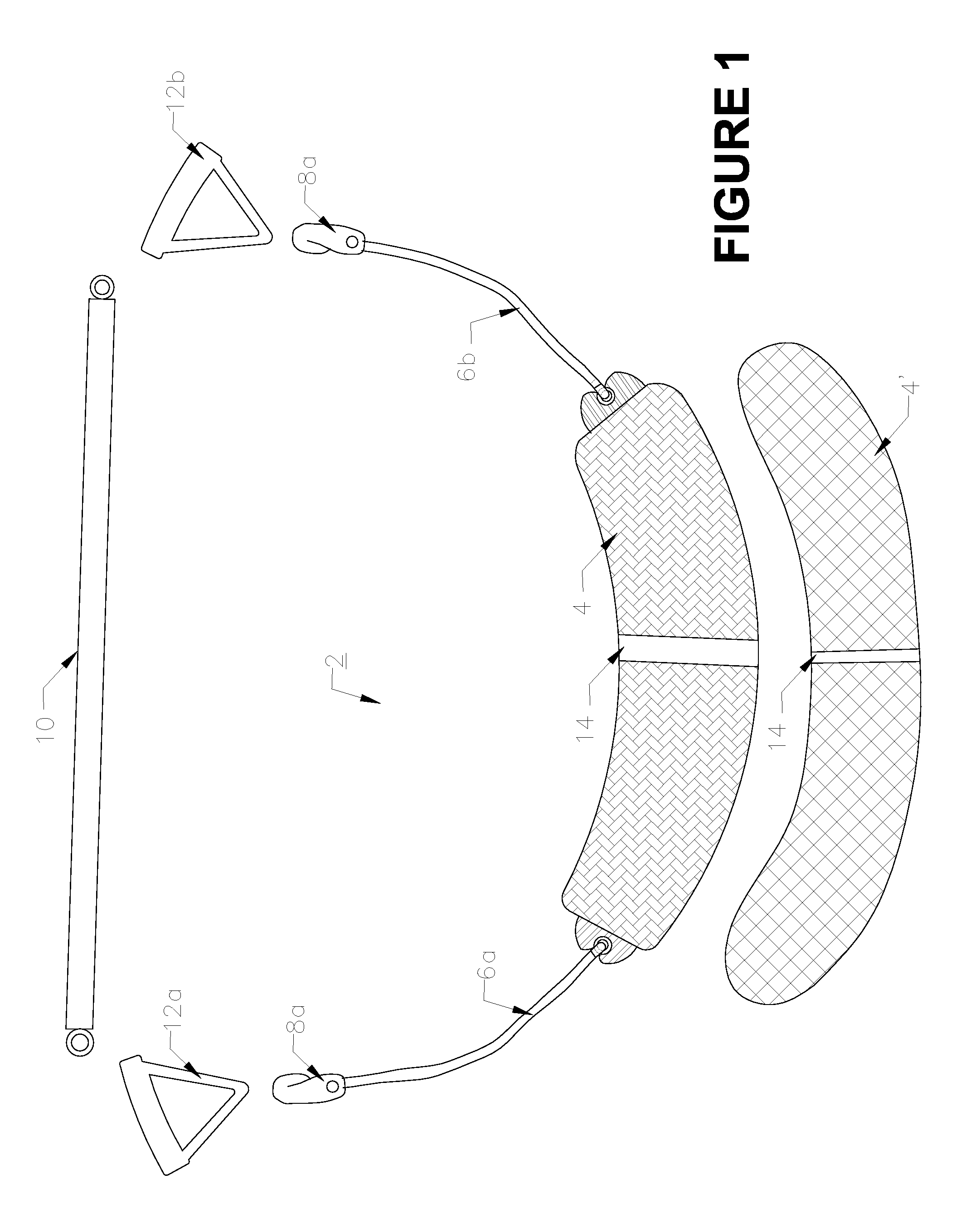
FIG. 1 illustrates the inventive resistance band exercise device 2. The resistance band exercise device 2 includes a portion 4 in the center which may be referred to as a safety net or Para-mount section. It is the device portion 4 that provides the wind resistance which will substantially reduce or eliminate the snap back effect in the event of a mount or placement failure causing an unwanted release of the center portion of the band 2. This device portion 4 can be made of a netting type of nylon material (as shown by element 4′), or may comprise an air impervious material 4, such as used in parachutes, and have a shape of approx 30″ in length and 6″-12″ in width so as to catch the air in the event the band snaps back. The device portion 4 is gathered at its opposing ends so as to form an overall cupped or parachute type of shape for the center section of the band 2, and the ends are securely attached to approximately 18″ to. 24″ inches of elastic band material 6a and 6b. Small cli...


PUM


Abstract

An elastic resistance band for use in an exercise device. The resistance band comprising a center portion having opposed ends and having a shape and comprised of a material which presents a substantial friction against air, so to create a wind resistance effect which slows down movement of the center portion when the center portion is forced to move through air, and an elastic band portion attached to each of the opposed ends of the center portion. The elastic band portions having at their free ends means for attaching the elastic resistance band to an exercise device.

Description

CROSS-REFERENCE TO RELATED APPLICATIONSThis application claims priority under 35 USC 120 of prior U.S. Provisional Patent Application U.S. Ser. No. 60 / 617,832, filed Apr. 18 2008. The entire disclosure of this patent application is incorporated herein by reference in its entirety.BACKGROUND OF THE INVENTION1. Field of the InventionThis invention relates generally, to exercise devices and more particular to the addition of a safety device for modifying the exercise resistance elastic bands.2. Description of the Prior ArtExercise devices of the type having elastic resistance bands are well know, see for example the exercise bar of U.S. Pat. No. 4,059,265. One drawback of an exercise device of this type having an elastic exercise band is the potential for a snap-back effect if the band breaks or slips off of a retaining position while it is stretched, which snap-back effect can cause the band 10 to hit the user or people nearby, thereby causing a severe bodily injury, as well as proper...

Claims


Application Information

Patent Timeline
Patent Type & Authority Patents(United States)
IPC IPC(8): A63B21/02
CPCA63B21/0552A63B21/1411A63B23/12A63B21/0088A63B21/0442A63B21/1645A63B23/0211A63B23/0233A63B2023/0411A63B2071/0072A63B2071/027A63B2208/0204A63B23/03525A63B23/03533A63B23/03541A63B23/1209A63B21/4005A63B21/4035
Inventor AYOUB, VICTOR R.
Owner AYOUB VICTOR R
Learn More