Method for assembling, identifying and controlling a powered surgical tool assembly assembled from multiple components

a technology of surgical tools and components, applied in the field of integrated systems for powered surgical tools, can solve the problems of increasing the overall time it takes for the procedure to be performed, improper input of characteristics, and limited amount of data

Inactive Publication Date: 2011-10-11
STRYKER CORP
View PDF48 Cites 1120 Cited by
  • Summary
  • Abstract
  • Description
  • Claims
  • Application Information

AI Technical Summary

Problems solved by technology

When surgical personnel have to do this during the course of a surgical procedure, it can increase the overall time it takes for the procedure to be performed.
Moreover, having to have an individual in the operating room set the surgical system to the operating characteristics of the cutting accessory that the system is being used to operate introduces the possibility that, due to human error, these characteristics will be improperly entered.
The above system, while of some utility, only provides a limited amount of data about the cutting accessory attached to the system handpiece.
This is because, due to space considerations, only a limited number of indicators can be mounted to a cutting accessory and only a limited number of sensors can be fitted in the head end of the handpiece designed to actuate the accessory.
Moreover, given the limited amount of data that can be read from the indicators of the current systems, these data may be insufficient to provide all the information a control console could use to regulate its operation based on the characteristics of the attached cutting accessory.

Method used


Image

  • Method for assembling, identifying and controlling a powered surgical tool assembly assembled from multiple components
  • Method for assembling, identifying and controlling a powered surgical tool assembly assembled from multiple components
  • Method for assembling, identifying and controlling a powered surgical tool assembly assembled from multiple components

Examples


Embodiment Construction

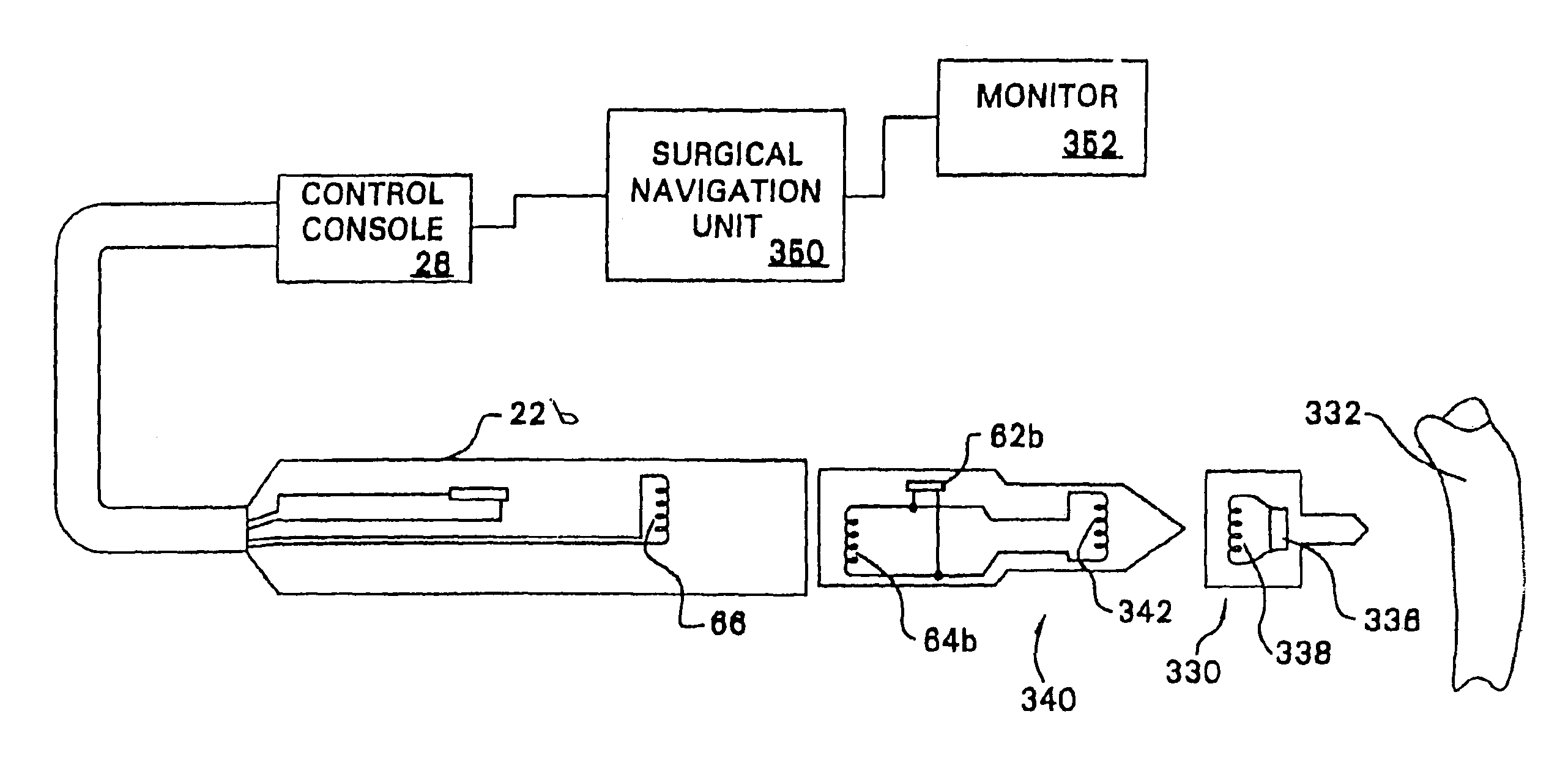
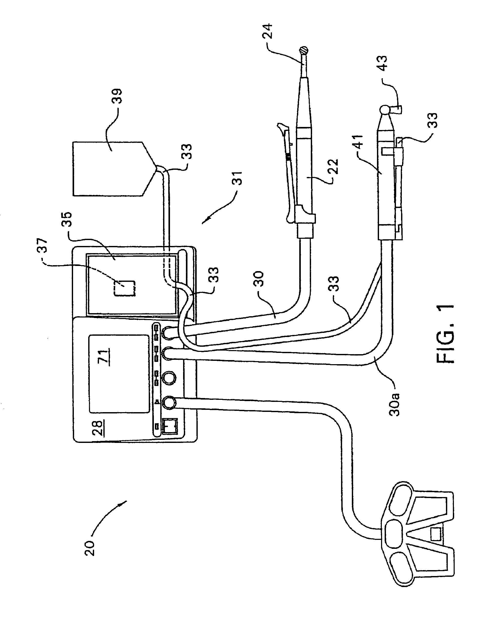
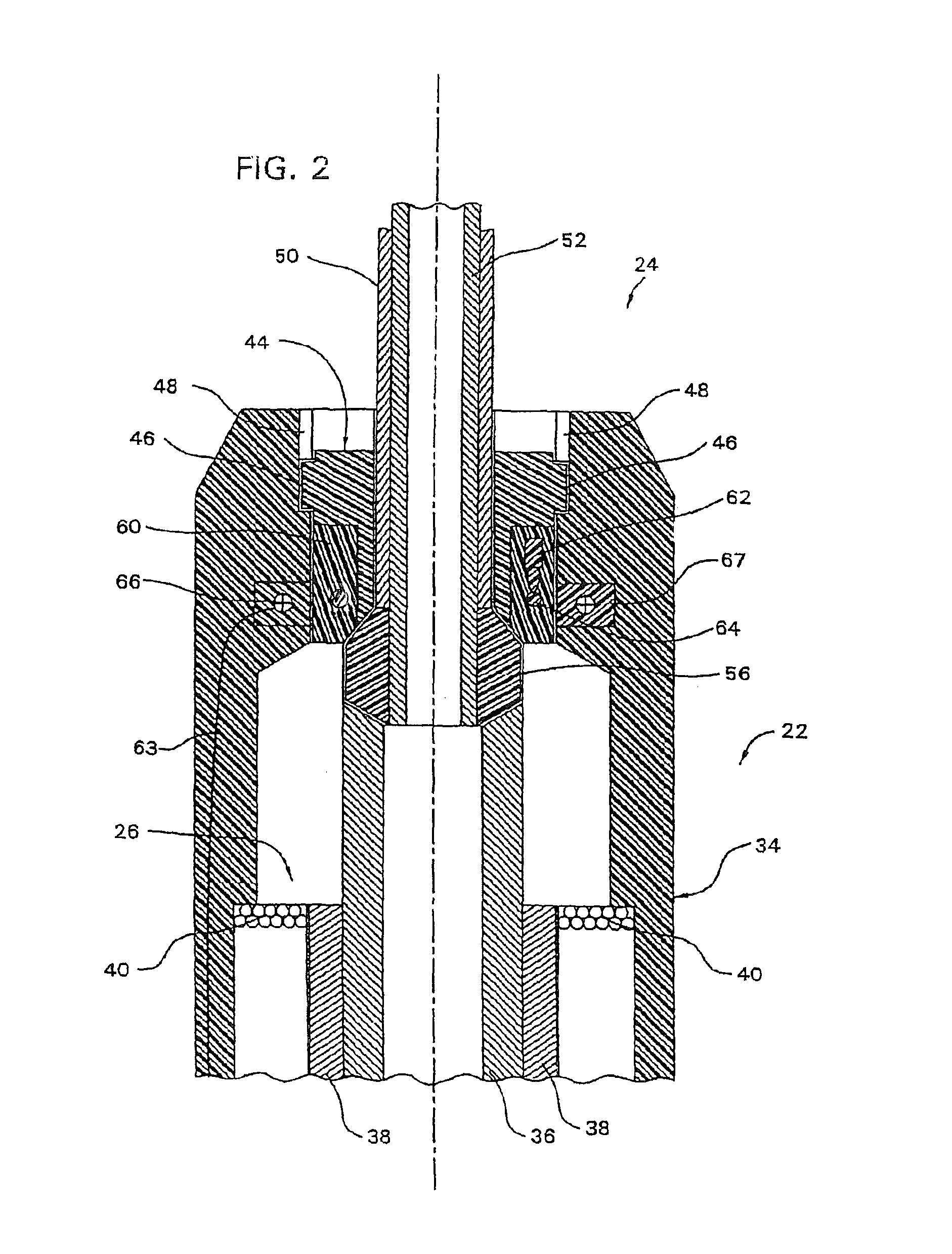
[0045]FIG. 1 depicts the surgical system 20 of this invention. System 20 includes a surgical handpiece 22 that is used to actuate a cutting accessory 24 that is removably attached to the handpiece. Internal to the handpiece is a motor 26 (FIG. 2) that is actuated to drive the cutting accessory 24. The handpiece 22 is removably attached to a control console 28 by a flexible cable 30. The control console 28 contains circuitry that is used to supply energization signals to the handpiece motor 26. The regulation of these energization signals is controlled by a microprocessor, controller 70 (FIG. 3), internal to the control console 28. Internal to the handpiece 22 or the cable 30 is a NOVRAM 32. (When the NOVRAM 32 is in the cable 30, the cable is integrally attached to the handpiece 22.) The NOVRAM 32 contains data that describes the operating characteristics of the handpiece 22. These data include: information that identifies the type of handpiece; information that describes the operat...


PUM


Abstract

A surgical tool system comprising a control console, a powered surgical device, an intermediate attachment removably connected to the surgical device and a cutting accessory removably connected to the intermediate attachment. Internal to the cutting accessory is an identification device that contains data specific to the operation of the accessory. The control console, through the transfer of signals through the powered surgical device and the intermediate attachment reads the data in the cutting accessory. Based on these data, the control console selectively actuates the powered surgical device. In some versions of the invention, the identification device may be an RFID chip. Signals are exchanged between the surgical device and the intermediate attachment and between the intermediate attachment and cutting accessory by inductive coupling. An identification device internal to the intermediate attachment provides the control console with data describing the intermediate attachment.

Description

RELATIONSHIP TO EARLIER FILED APPLICATIONS[0001]This Application is a continuation of application Ser. No. 10 / 214,937, filed Aug. 8, 2002, now abandoned, which claims priority from the Applicant's U.S. Patent Application Ser. No. 60 / 310,957, SURGICAL TOOL SYSTEM WITH A CUTTING ACCESSORY THAT CONTAINS A MEMORY WITH DATA THAT DESCRIBES THE OPERATING CHARACTERISTICS OF THE CUTTING ACCESSORY, filed Aug. 8, 2001. The contents of the above-listed applications are explicitly incorporated herein by reference.BACKGROUND OF THE INVENTION[0002]The Applicant's Assignee's U.S. Pat. No. 6,017,354, entitled INTEGRATED SYSTEM FOR POWERED SURGICAL TOOLS, issued Jan. 25, 2000, and incorporated herein by reference, describes a surgical tool system with a handpiece that is removably attached to a control console. Internal to the handpiece is a memory, a NOVRAM. The NOVRAM contains data that describes the operating characteristics of the handpiece. For example, if the handpiece includes a motor, its NOV...

Claims


Application Information

Patent Timeline
Patent Type & Authority Patents(United States)
IPC IPC(8): H04Q5/22A61B17/00A61B17/14A61B17/16A61B17/32A61B19/00G06K17/00
CPCA61B17/1626A61B17/1688A61B17/32002A61B19/5244A61B17/8875A61B17/162A61B19/38A61B2017/00017A61B2017/00221A61B2017/00464A61B2017/00477A61B2017/00482A61B2019/448A61B2019/4821A61B2019/502A61B2019/566A61B2217/005A61B2217/007G06K2017/009A61B2090/0804A61B2034/102A61B2034/256A61B34/20A61B90/40A61B90/98
Inventor MALACKOWSKI, DON
Owner STRYKER CORP
Why Eureka
Try Eureka