Calibration scheme for an exhaust gas sensor

a technology of exhaust gas and calibration scheme, which is applied in the field of gas sensor, can solve the problems of measurement error, inability to accurately determine and gasses in the vicinity of the sensor may not have enough time to reach a steady state, etc., and achieve the effect of accurately determining the gain and/or offset of the sensor

Inactive Publication Date: 2011-10-11
FORD GLOBAL TECH LLC
View PDF7 Cites 9 Cited by
  • Summary
  • Abstract
  • Description
  • Claims
  • Application Information

AI Technical Summary

Benefits of technology

[0004]As such, in one approach, the above issue may be at least partially addressed by projecting an equilibrium value of a desired exhaust gas constituent reading of the exhaust gas sensor, such as during transient DFSO conditions where the sensor is exposed to a mixture of ambient air and exhaust gas. For example, during engine non-fueling conditions such as DFSO, an equilibrium value may be generated based on a trajectory of an exhaust gas constituent reading of the exhaust gas sensor. Specifically, generating the equilibrium value of the exhaust gas constituent reading based on the trajectory may include applying a projection model to a plurality of successive exhaust gas constituent readings taken during the engine non-fueling conditions. In this manner, the equilibrium value of an exhaust gas constituent may be estimated, and thus gain and / or offset of the sensor may be accurately determined, even if gasses in the vicinity of the sensor have not reached a steady state corresponding to ambient air.

Problems solved by technology

Over time, however, sensor parameters can drift resulting in measurement error.
However, the inventors herein have recognized a problem with this method.
Specifically, during DFSO, the gasses in the vicinity of the sensor may not have enough time to reach a steady state (e.g., equilibrium) of ambient conditions as DFSO has a limited duration.
For this reason, it may not be possible to correctly determine gain and offset of the sensor and, therefore, calibrate the sensor to provide accurate readings of exhaust gas constituents.

Method used


Image

  • Calibration scheme for an exhaust gas sensor
  • Calibration scheme for an exhaust gas sensor
  • Calibration scheme for an exhaust gas sensor

Examples


Embodiment Construction

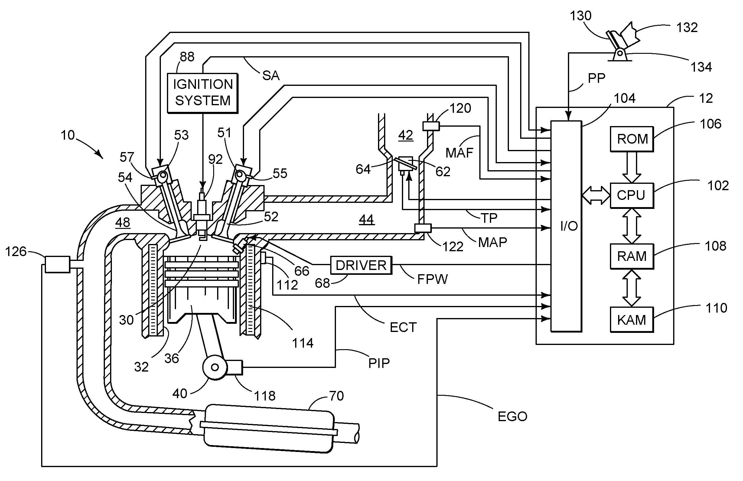
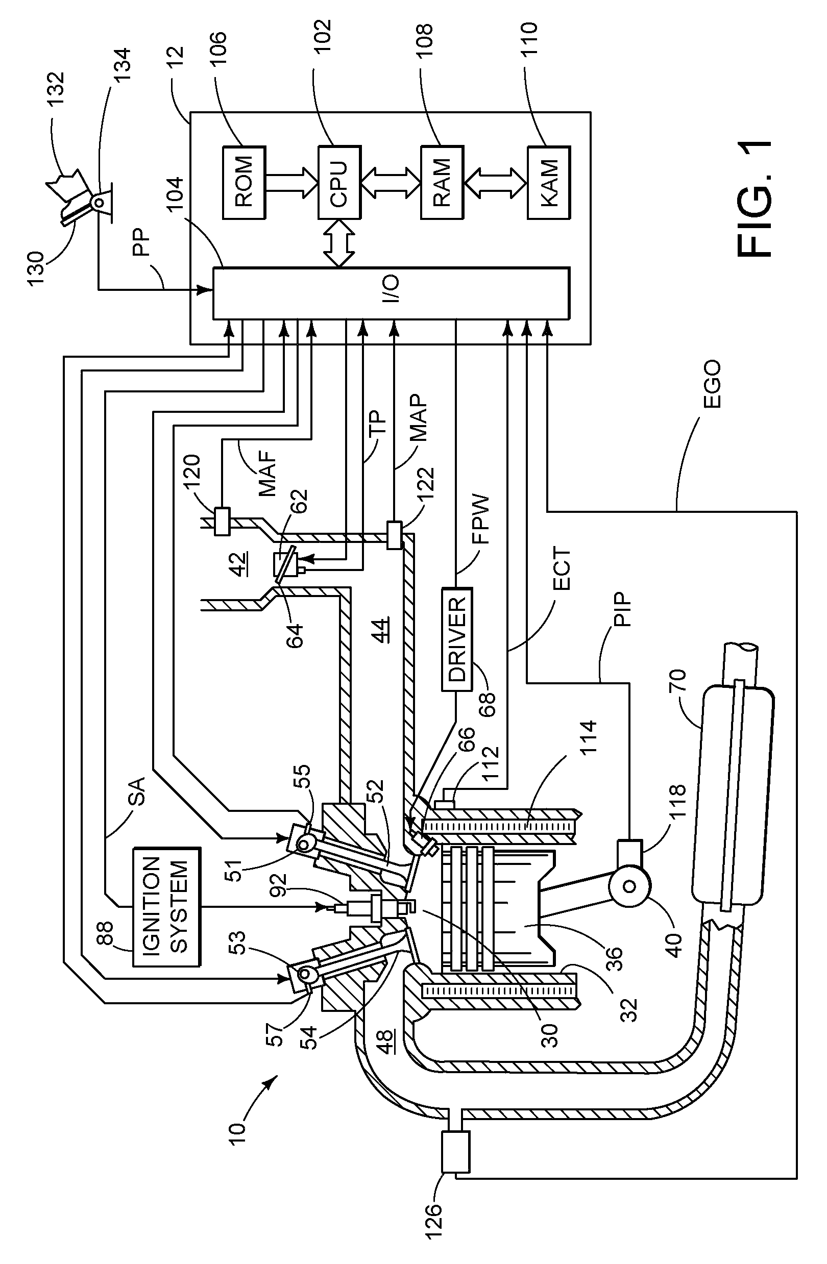
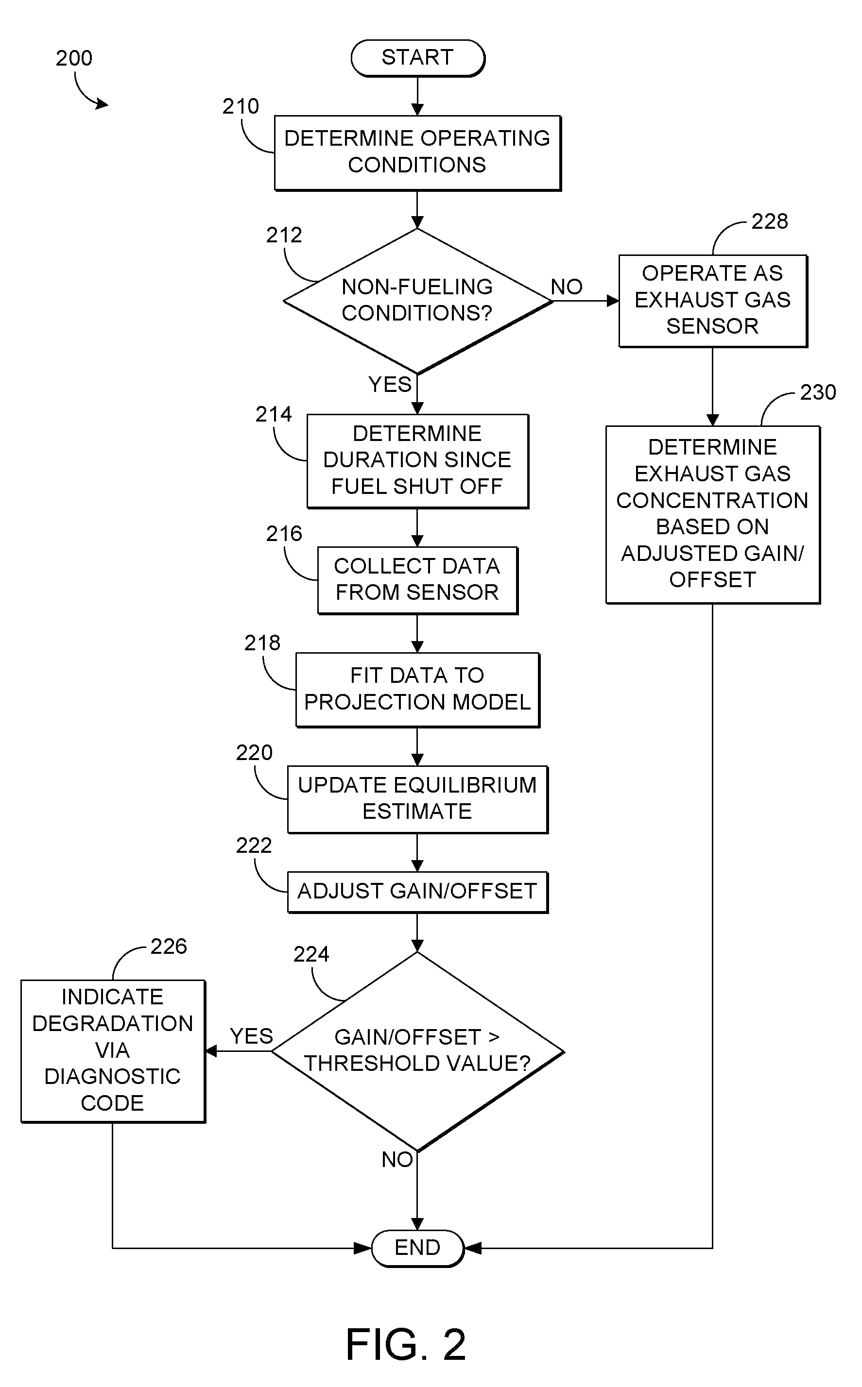
[0010]The following description relates to a method for controlling an engine in a vehicle wherein a control system is configured to adjust one or more engine operating parameters based on an equilibrium value of an exhaust gas constituent reading generated by an exhaust gas sensor, such as a NOx reading of a NOx sensor. The equilibrium value may be obtained during engine non-fueling conditions such as deceleration fuel shut off (DFSO) in which the gasses in the exhaust gas are those of ambient air and concentrations of the gas constituents are known to a certain extent. Since the duration of DFSO may not be long enough for the gasses to reach a steady state of ambient air in the vicinity of the sensor, the equilibrium value of the exhaust gas constituent reading may be projected, since the trajectory may follow a repeatable pattern governed by exhaust mixing, etc. In some embodiments, a trajectory of the exhaust gas constituent readings may be generated by fitting a plurality of th...


PUM


Abstract

Various systems and methods are described for controlling an engine in a vehicle in response to an equilibrium value of an exhaust gas constituent generated from an exhaust gas sensor. One example method comprises during engine fueling below a threshold amount where at least one intake valve and one exhaust valve of the engine are operating: generating an equilibrium value of an exhaust gas constituent reading of the exhaust gas sensor, the equilibrium value based on a trajectory of the exhaust gas constituent reading, and under selected engine combusting conditions, adjusting the sensor signal based on the equilibrium value.

Description

TECHNICAL FIELD[0001]The present description relates generally to a gas sensor for measuring exhaust gas constituents from an internal combustion engine.BACKGROUND AND SUMMARY[0002]When new, gain and offset of exhaust gas sensors may be determined in order to calibrate the sensor so that accurate measurements of exhaust gas constituents may be obtained. Over time, however, sensor parameters can drift resulting in measurement error. For example, a sensor gain and offset, which are calibration parameters used to define a linear transformation from sensor output to a measured parameter, may drift during sensor operation. Thus, periodic updates of the sensor parameters, including sensor gain and offset, during the lifetime of the sensor may be used.[0003]One method to calibrate the sensor during its lifetime in a motor vehicle includes measuring gain and offset during a period when the concentration of a desired gas constituent is known, such as deceleration fuel shut off (DFSO) when th...

Claims


Application Information

Patent Timeline
Patent Type & Authority Patents(United States)
IPC IPC(8): F02D45/00F01N11/00
CPCF01N11/00F02D41/123F02D41/1462F02D41/2416F02D41/2454F01N2560/025F01N2560/026F02D41/1452F02D41/1454F02D41/1456F02D41/1459F02D41/146F02D2041/1433F02D2041/1468Y02T10/47Y02T10/40
Inventor WEBER, DAVE CHARLESKUBINSKI, DAVID JOHNHE, CHUANVAN NIEUWSTADT, MICHIEL J.
Owner FORD GLOBAL TECH LLC
Why Eureka
Try Eureka