Spray gun having display and control members on gun

a control member and gun technology, applied in the direction of electric controllers, mechanical control devices, instruments, etc., can solve problems such as loss of production tim

Active Publication Date: 2011-10-18
NORDSON CORP
View PDF12 Cites 23 Cited by
  • Summary
  • Abstract
  • Description
  • Claims
  • Application Information

AI Technical Summary

Benefits of technology

[0005]In accordance with another inventive aspect of the disclosure, a display and control function are provided for a material application device such that an operator action is enabled to select a coating operation parameter during operation of the material application device, and optionally during a coating material application operation. In one embodiment, a manually actuated device may be associated with the material application device so that the operator may make a selection and view and confirm the choices and selection made on the display. In another embodiment, the manually actuated device may be realized for example in the form of a finger actuated trigger disposed on the handgrip of a manually controlled material application device or spray gun. The combined functionality of a display on the spray gun and a selection function enables, in one embodiment, an operator to make selections of one or more coating operation parameters without having to divert attention or view away from the spray gun or coating operation. In still another embodiment, the combined functionality of a display and a selection function enables an operator to make selections of one or more coating operation parameters with a single hand, including the hand being used by the operator to support or hold the manually operated material application device.

Problems solved by technology

Such changeovers result in lost production time.

Method used


Image

  • Spray gun having display and control members on gun
  • Spray gun having display and control members on gun
  • Spray gun having display and control members on gun

Examples


Embodiment Construction

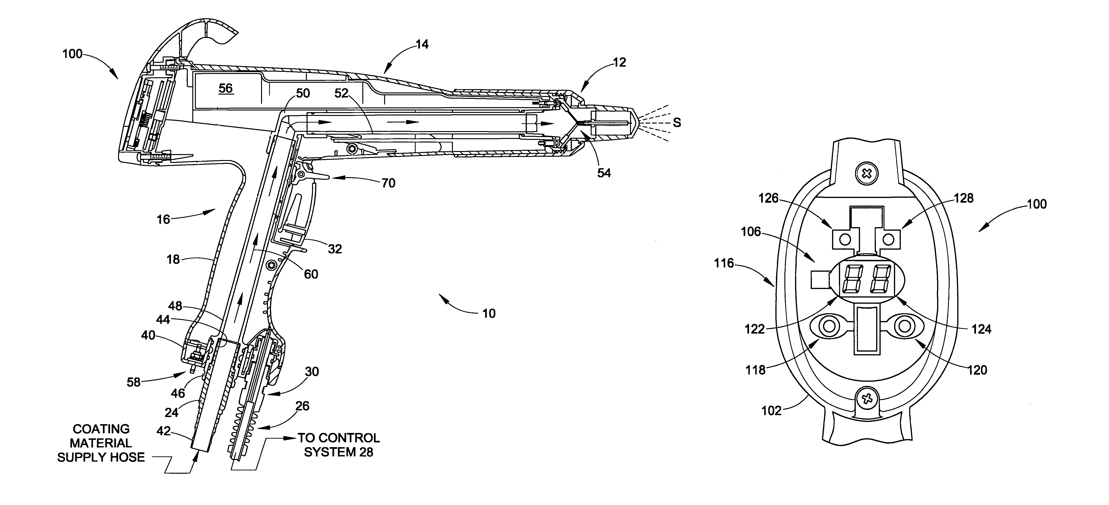
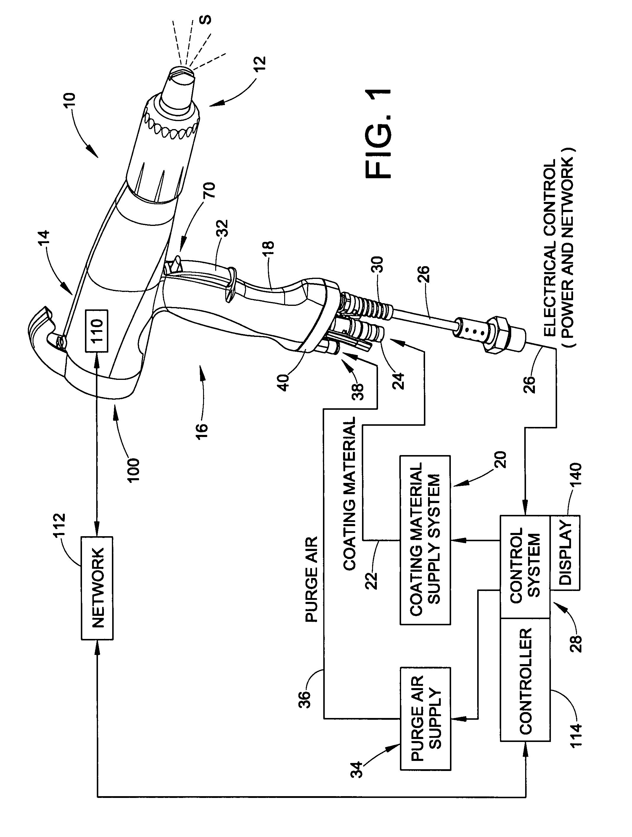
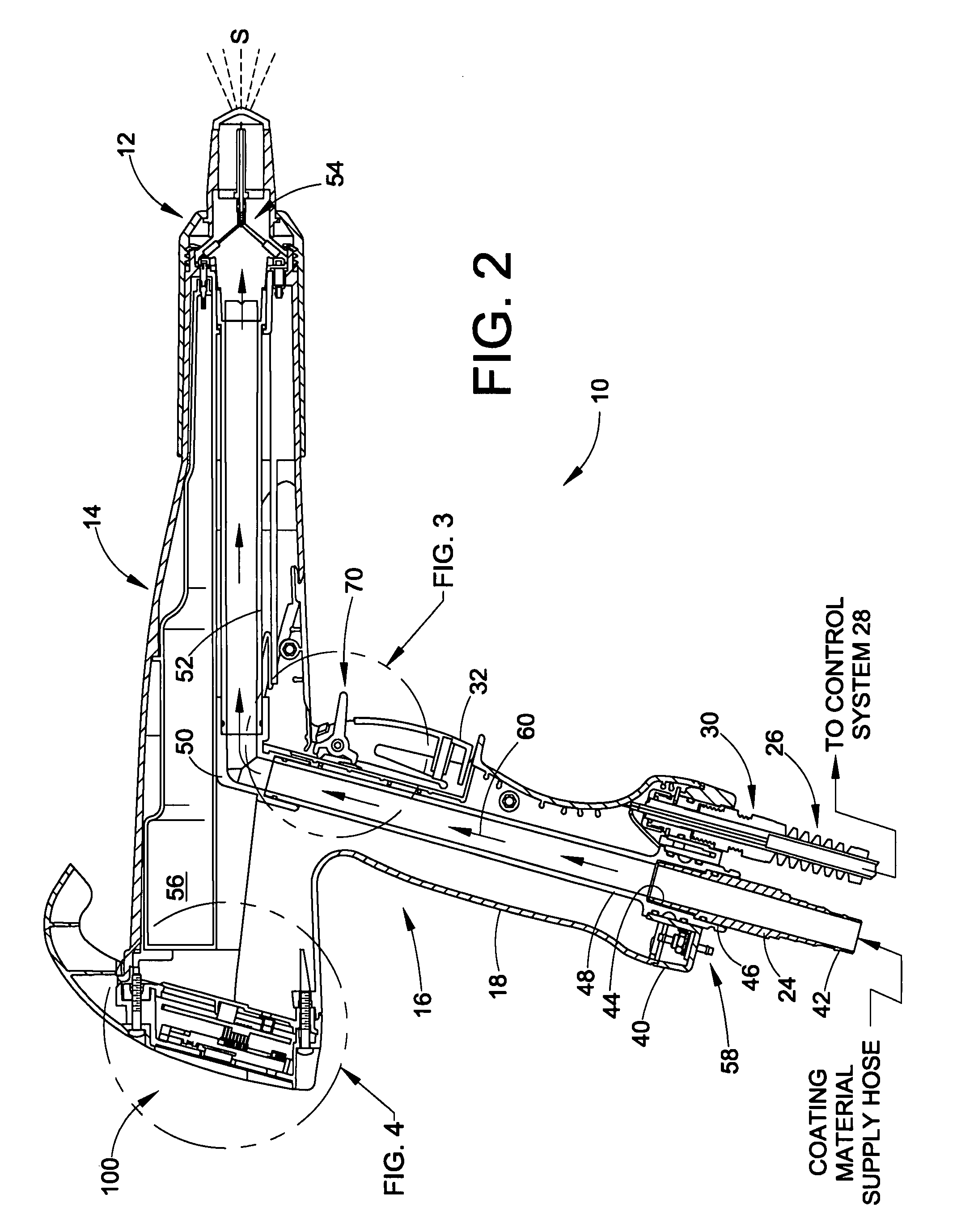
[0018]The inventions described herein are explained and illustrated in the context of a powder coating material application device, such as, for example, an electrostatic powder spray gun. However, the exemplary embodiments are not intended to be a limitation on the application or use of the various inventive aspects presented in this disclosure. For example, the inventions may be used with non-electrostatic material application devices and with tribo-charging guns that do not utilize an electrode, or combinations thereof. The inventions also are not limited to any particular type or use of coating material. Additionally, the terms ‘spray’ and ‘spray pattern’ are intended to be understood in their broadest meaning to include not only those processes commonly referred to as ‘spray’ or ‘spraying’ but additionally any application technique involving the directing of a generally dry particulate coating material across a space towards a target. The spray pattern may be but need not be at...


PUM

PropertyMeasurementUnit
flow rateaaaaaaaaaa
coloraaaaaaaaaa
production timeaaaaaaaaaa

Abstract

Control method and apparatus for a manual spray gun includes display that is disposed on the spray gun and that provides information to an operator about one or more coating operation parameters. An auxiliary trigger may be used that enables an operator to make selections or changes of one or more coating operation parameters. The display and auxiliary trigger together permit an operator to make selections or changes without having to divert attention or field of view away from the spray gun or the coating area, especially during a coating operation. The display may include numeric information, for example, data relating to a coating function being displayed.

Description

TECHNICAL FIELD OF THE DISCLOSURE[0001]The disclosure relates to the art of applying material onto surfaces, such as for example, spraying or coating a surface with a coating material. More particularly, the disclosure and inventions relate to arrangements and methods for controlling a material application device such as a spray gun.BACKGROUND[0002]Powder coating material such as powder paint is commonly applied to an object by spraying the powder coating material. Typically, a spray gun or material application device is used, and spray guns may be manually held and operated or automatic spray guns may be used that are controlled electronically. Spray technologies include for example electrostatic, non-electrostatic and tribo-electric. The powder flow path through a spray gun must be purged whenever the powder coating material, such as its color or other characteristic, is changed, in order to prevent unwanted contamination. In addition, spray parameters are commonly changed for dif...

Claims


Application Information

Patent Timeline
Patent Type & Authority Patents(United States)
IPC IPC(8): B05C11/00G05B11/01B05C19/00
CPCB05B5/032B05B5/053G05G1/04B05B12/002B05B12/008G05G1/01B05B9/01B05B5/047B05B5/1683B05B7/1486B05B15/025B05B15/55B05D1/06G06F3/04847G06F3/0485
Inventor MATHER, BRIANPERKINS, JEFFREY A.
Owner NORDSON CORP
Why Eureka
Try Eureka