Magnetically attachable window screen system

a window screen and magnetic technology, applied in the field of magnetically attachable window screen systems, can solve the problems of difficult to determine precisely where the retaining posts are, the use of retaining posts is an awkward way to install and uninstall window screens, and the post release is often not sufficien

Active Publication Date: 2011-10-18
ALKHOURY BOULOS PAUL +1
View PDF35 Cites 20 Cited by
  • Summary
  • Abstract
  • Description
  • Claims
  • Application Information

AI Technical Summary

Problems solved by technology

Unfortunately the use of retaining posts is an awkward way to install and uninstall window screens from casement windows.
Retaining post biasing means are typically concealed within the window screen and it is difficult to determine precisely where the retaining posts are positioned in that the position of retaining posts is typically not visible once the window screens have been installed in a casement window.
When attempting to pull a window screen directly forward in an attempt to remove the window screen, the posts are often not released sufficiently by the biasing means to permit the screens to be removed without some guess work.
Often users are unable to remove the window screens and help is sought by the user.
Although some window screens for casement windows have pull tabs, the use of such tabs is not universal due to additional cost of parts and manufacture and which tabs detract from the clean lines of the window frame sides.
Although somewhat easier to use than the window screen frames without tabs, multiple retaining posts with multiple tabs are usually used, leaving the user with the frustrating task of typically pulling inwardly on two opposing tabs and then having to somehow pull inwardly on a second set of retaining tabs before the screen will be released.
This often results in the user having to flex the window screen forward so the first set of tabs may be released so the user may release the seconds or subsequent set of typically opposing pull tabs.
Flexing such window screens may be difficult or may damage the window screen, or at least give the user some apprehension as to whether or not the screen would be damaged using such a removal technique.
Some prior art Patents have experimented with the use of magnets for holding a screen against a window aperture, such attempts have been crude and not adapted for use with casement windows.
Such attempts appear to be restricted to surface mounting magnets to the window frames of older style windows.
Although the magnets in some prior Patents have been hidden when window screens have been installed thereon, the magnets, or corresponding metal pieces against which magnets may operate typically remain on the frames which are unsightly when a window screen is not in position.
Such unsightly appearance is completely incongruous with the clean lines of current plastic casement windows.
Thus far, a way of mounting magnets within casement windows, and in particular, within one of the various channels provided by casement windows has not been invented.
Furthermore, as an adequate alternative to the use of retaining posts and cooperating slots in a casement window frame has not yet been invented, it has not been possible to eliminate the retaining post slots, which not only are inconsistent with the clean lines of current day casement windows, but are also a catch all for dust, dirt, food, drink, debris and bacteria, which are almost impossible to completely clean given that the typical post slots are a passage to a typically larger channel within the casement window frame.
This is especially a problem for the slot in the lower horizontal window frame member into which contaminants may fall due to the force of gravity.
Regardless of the above-mentioned disadvantages relating to the use of the slot and post method of screen retention for casement windows, no adequate way of magnetically attaching window screens to casement windows has yet been invented.

Method used


Image

  • Magnetically attachable window screen system
  • Magnetically attachable window screen system
  • Magnetically attachable window screen system

Examples


first embodiment

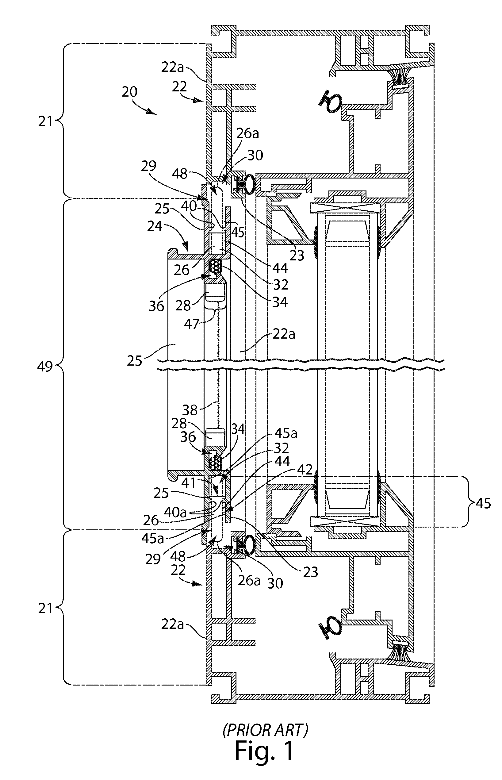
[0029]FIG. 3 is a vertical sectional view of a magnetically attachable window screen system. Magnetic window screen (with post cavity foot) 50 is for use with prior art window frame 22 which comprises slotted post cavity 30 and post cavity slot 48. Lower horizontal screen bar 52 has a post cavity foot 66 for insertion into slotted post cavity 30 through post cavity slot 48 for supporting the weight of magnetic window screen 50 and thus preventing window screen insert 47 from slipping out of window screen opening 49. Those skilled in the art will recognize that window screen insert 47 need not be between side perimeter walls 23 in this and similar embodiments unless the window screen insert 47 is used to support the window screen. As the side profile of lower horizontal screen bar 52 post cavity foot 66 would typically constitute one long foot running almost the entire length of lower horizontal screen bar 52 as shown in FIG. 4. FIG. 4 shows the ends of post cavity foot 66 which may ...

second embodiment

[0040]FIG. 7 is a horizontal sectional top view of the magnetically attachable window screen system showing lip foot 84 overhanging and engaging support lip 82.

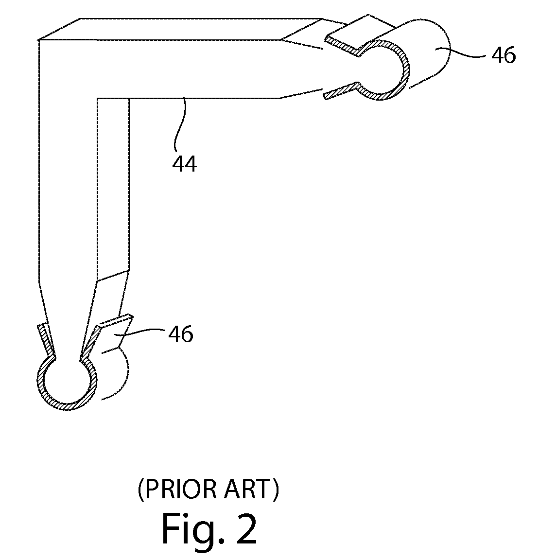
[0041]Magnetic window screen 71 also contain corner key cavities 58 for receiving corner keys 44 at the ends of screen bars 54, 56, 88. FIG. 7 also shows a typical gasket cavity 36 for receiving screen gasket 34 for holding screen mesh 38 in place. The sides of screen magnet cavity 64 again act as spacers 68 and may perform this function whether or not screen magnets 62 are inserted in screen magnet cavities 64.

[0042]FIG. 8 is a vertical sectional view of a third embodiment of the magnetically attachable window screen system, showing the window frame 72 of FIGS. 6 and 7, however, lips 82, 86 are not required in this embodiment and treated as decorative only in this third embodiment. Side perimeter wall 23 of lower horizontal side 76 of window frame 72 acts as a ledge for receiving screen frame support surface 94 for supportin...

third embodiment

[0044]FIG. 9 is a horizontal sectional top view of the magnetically attachable window screen system showing vertical screen bars 90 with screen magnet cavities 64 without magnets 62 therein and vertical frame magnet cavities 80 without magnets 60 therein. As previously recited magnets 62, 60 may be used within vertical cavities 64, 80 respectively if extra strength is required or to prevent bowing of screen bars 90. The height and width of window screen insert 47 of window screen 89 are slightly smaller than the height and width of window screen opening 49 of window frame 72 to prevent binding in the event of minor expansion of window parts.

[0045]In embodiments one to three aforementioned screen magnets 62 in screen magnet cavities 64 mounted against front perimeter walls 21 co-operate with corresponding frame magnets in a substantially horizontal manner. In the fourth, fifth and sixth embodiments described for below the magnets within the screen bars and magnets within the window f...


PUM


Abstract

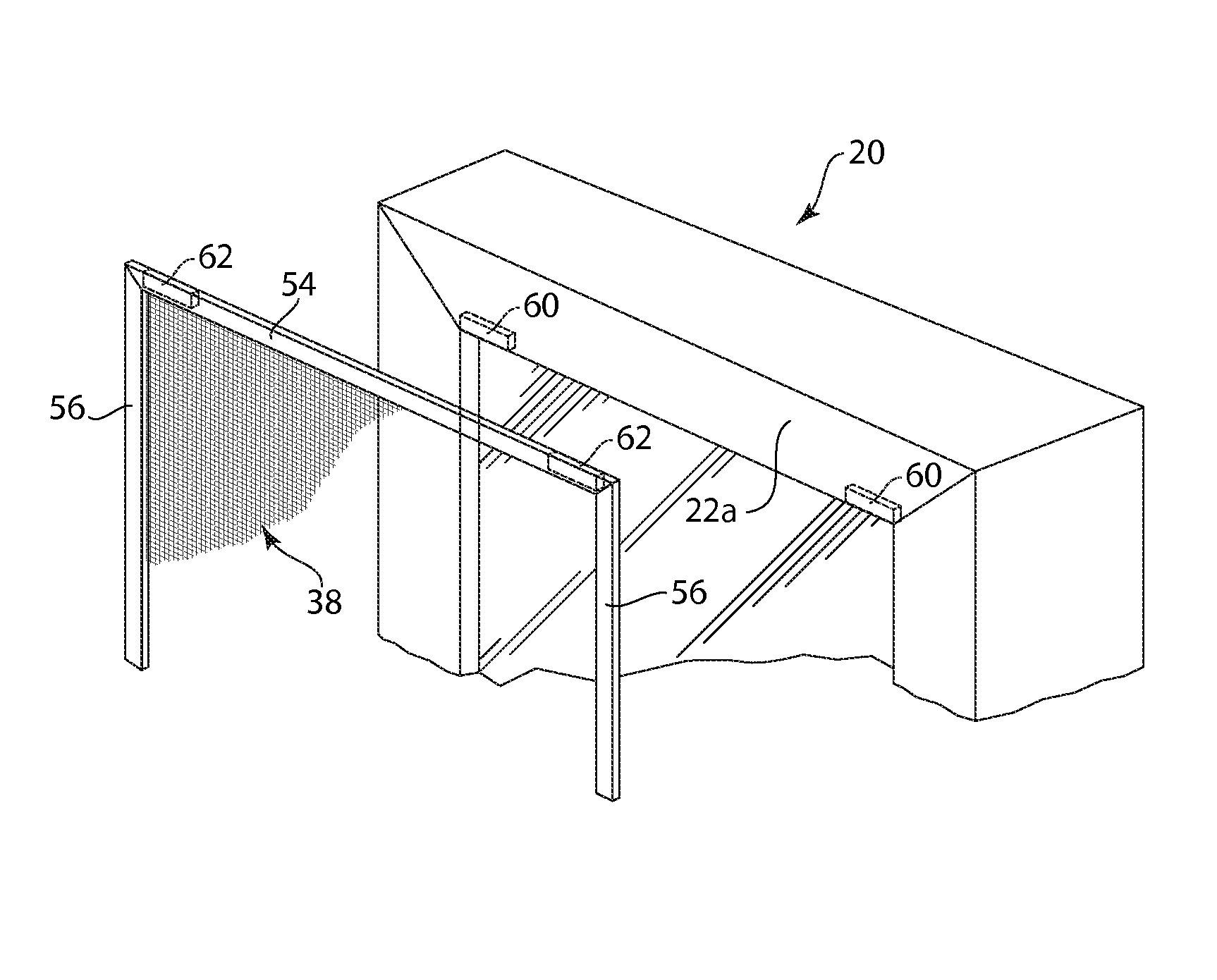
A magnetically attachable window screen system comprising,a rectangular casement window comprising a casement window frame for removably attaching a rectangular window screen, the casement window frame comprising four window frame sides,the four window frame sides comprising a lower horizontal frame side, an upper horizontal frame side and two opposing vertical frame sides, each window frame side comprising a front perimeter wall and a side perimeter wall, at least one frame magnet attached to the casement window frame at least partly behind the plane defining the front perimeter wall or the plane defining the side perimeter wall, at least one support on the casement window frame for supporting the window screen, the window screen comprising a screen frame comprising four screen bars, the four screen bars comprising a lower horizontal screen bar, an upper horizontal screen bar, and two vertical screen bars, the window screen further comprising at least one screen magnet attached to the window screen frame and positioned to magnetically co-operate with the at least one frame magnet attached to the casement window frame.

Description

FIELD OF THE INVENTION[0001]This Invention relates to a system for mounting window screens. In particular, this invention relates to a system for magnetically attaching window screens to casement windows.BACKGROUND OF THE INVENTION[0002]Casement windows currently used in the construction of new residential dwellings, and as an aftermarket product in renovations, typically contain a window frame of extruded plastic or the like. In order to reduce the weight of the window frame, and the cost of material, casement window frames are typically constructed with a plurality of interior walls resulting in a plurality of channels which typically run longitudinally along the entire length of each piece of straight window frame.[0003]In order to attach a prior art window screen to a prior art casement window, the walls of the window frame against which the window screen is to be mounted are typically provided with a slot in the window frame sides bounding the sides of the window screen to be i...

Claims


Application Information

Patent Timeline
Patent Type & Authority Patents(United States)
IPC IPC(8): E06B9/52A44B99/00
CPCE06B9/52Y10T24/32Y10S160/16
Inventor ALKHOURY, BOULOS PAULD'UVA, PASQUALINO
Owner ALKHOURY BOULOS PAUL
Why Eureka
Try Eureka