Encapsulated endoscope
a technology of endoscope and endoscope, which is applied in the field of encapsulated endoscope, can solve the problems of the shutter function provided at an ordinary mos imaging devi
- Summary
- Abstract
- Description
- Claims
- Application Information
AI Technical Summary
Benefits of technology
Problems solved by technology
Method used
Image
Examples
first embodiment
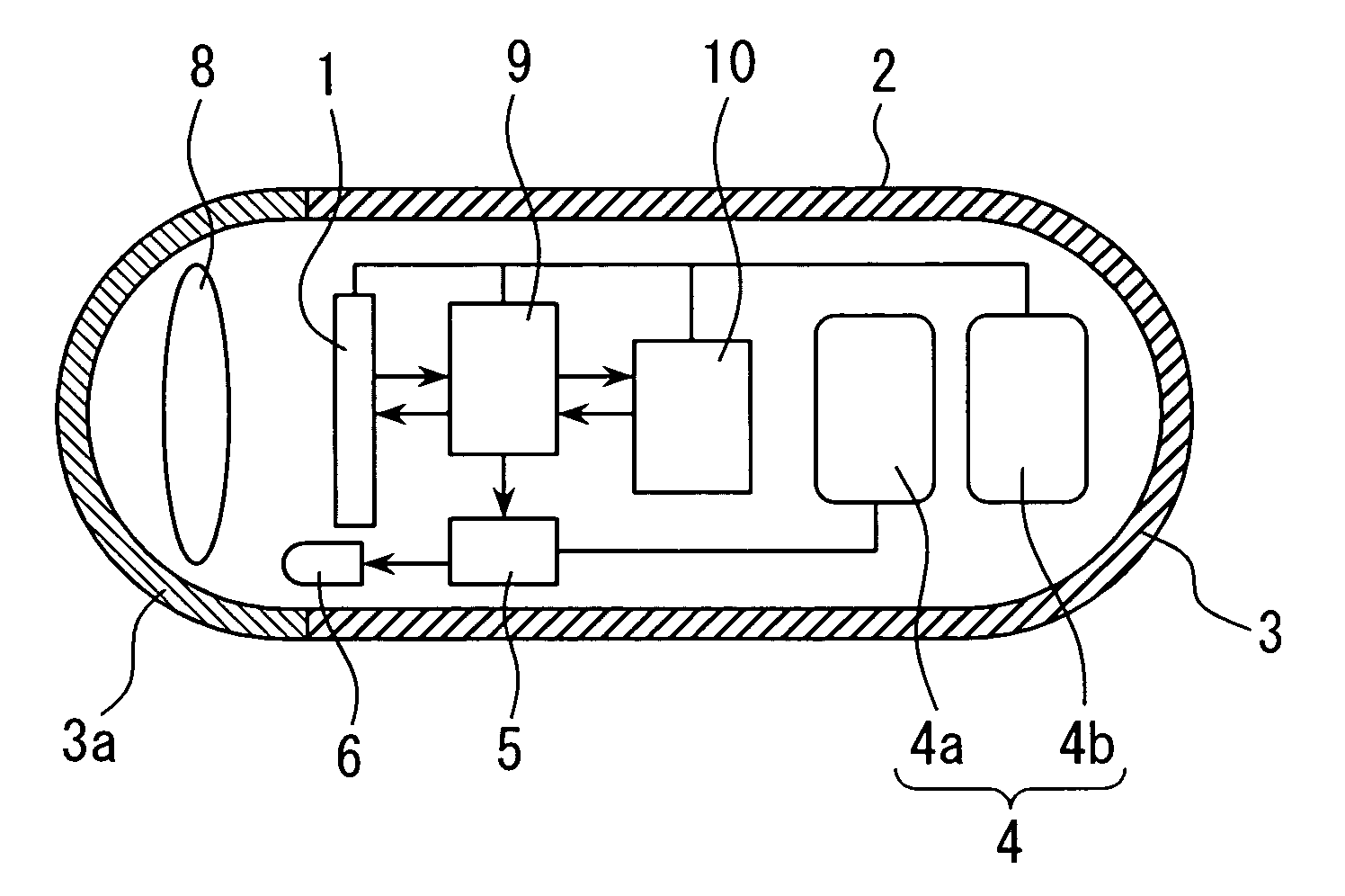
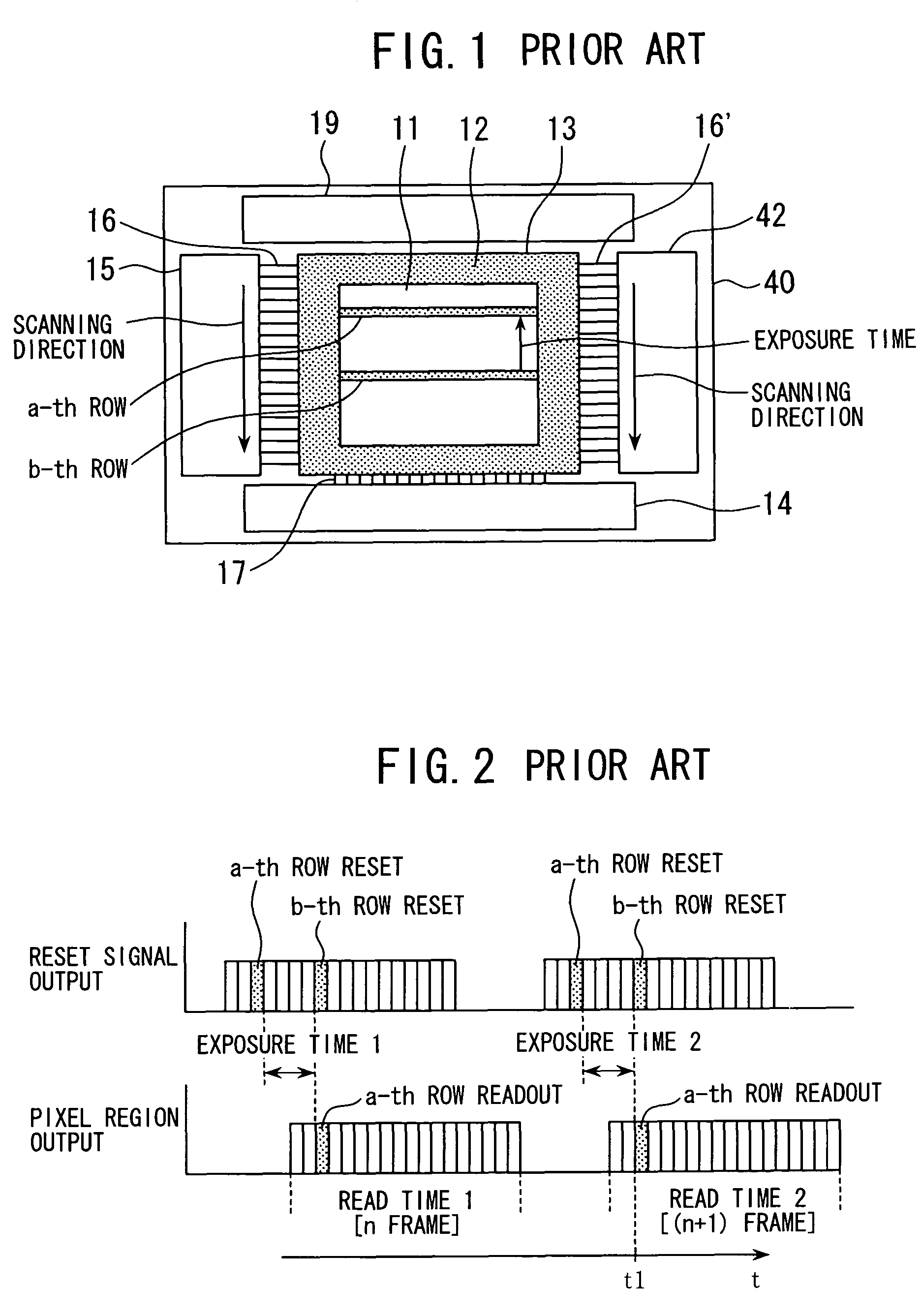
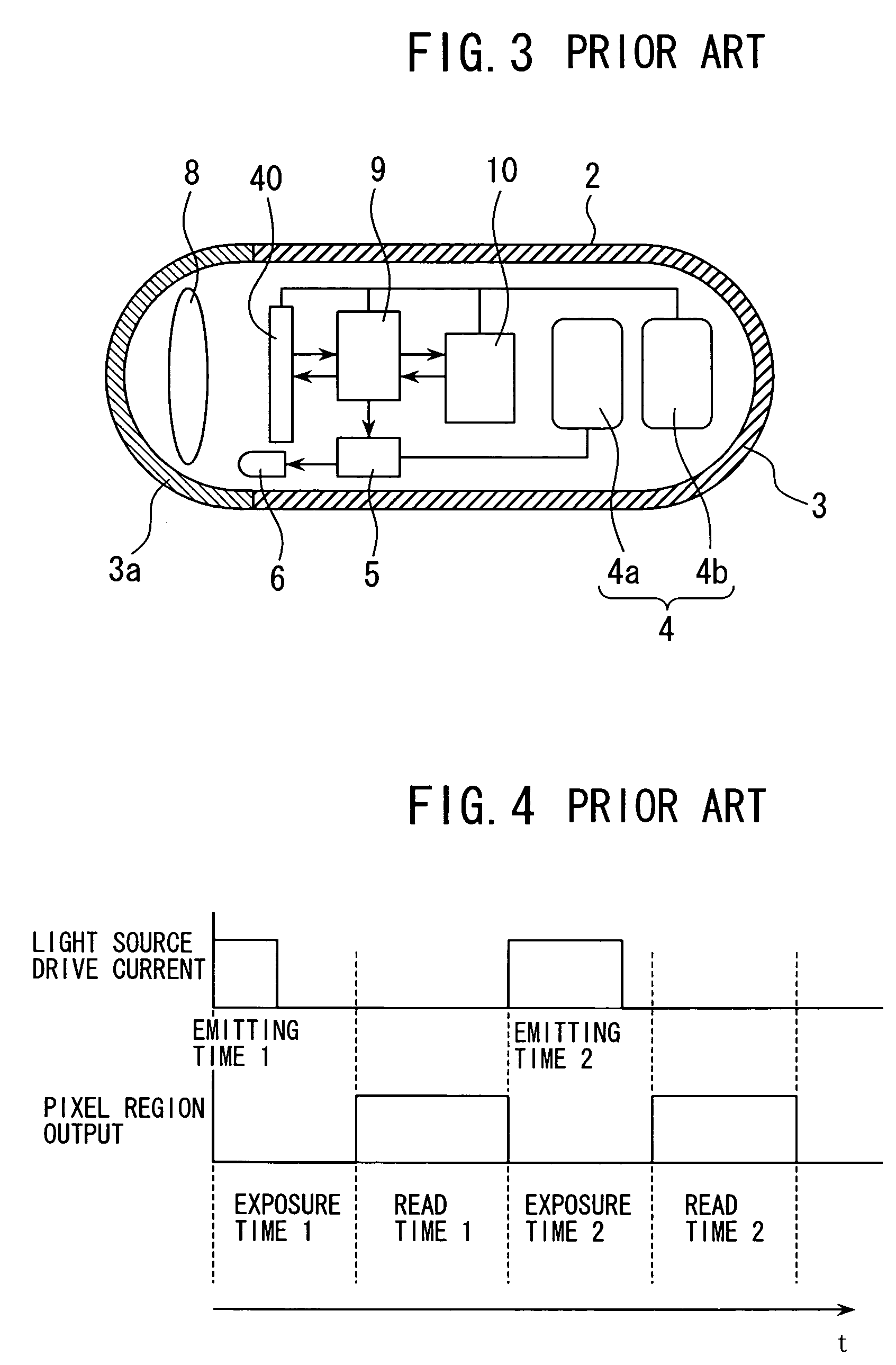
[0027]A description will be given below of some embodiments with reference to the drawings. A first embodiment of the encapsulated endoscope according to the present invention will now be described. FIG. 5 is a block diagram schematically showing construction of the electrical circuit of an encapsulated endoscope 2 according to the first embodiment, where like or corresponding components as in the prior-art encapsulated endoscope 2 shown in FIG. 3 are denoted by like reference numerals. The construction and drive operation of the encapsulated endoscope according to the first embodiment shown in FIG. 5 are substantially identical to the construction and drive operation of the prior-art encapsulated endoscope shown in FIG. 3, and MOS image sensor 1 is suitably used as the area sensor therein. Further, since exposure amount thereof is controlled at the light source side, an exposure amount control at MOS image sensor 1 is not to be effected.
[0028]FIG. 6 is a block diagram schematically...
second embodiment
[0030]A second embodiment of the invention will now be described. FIG. 7A is a block diagram schematically showing construction of the electrical circuit of an encapsulated endoscope 2 according to the second embodiment, where like or corresponding components as in the encapsulated endoscope according to the first embodiment shown in FIG. 5 are denoted by like reference numerals. The construction and drive operation of the encapsulated endoscope according to the second embodiment is identical to the construction and drive operation of the encapsulated endoscope according to the first embodiment shown in FIG. 5. FIG. 7B shows a front view as seen from the object side of the encapsulated endoscope 2 according to the second embodiment shown in FIG. 7A, where the center of MOS image sensor 1 is denoted by numeral 31, the center of the light-receiving pixel region 11 of the pixel section 13 by 32, the central axis of the encapsulated endoscope 2 by 20, and the center of the objective len...
third embodiment
[0035]A third embodiment of the invention will now be described. FIG. 9 is a block diagram showing construction of MOS image sensor 1 to be mounted on an encapsulated endoscope 2 according to the third embodiment. The MOS image sensor 1 according to the third embodiment includes: a pixel section 13 having a plurality of pixels two-dimensionally disposed in rows and columns: a first vertical scanning unit 23 for selecting odd rows to be read of the pixel signals of the pixel section 13 and for sequentially switching the row to be selected; a first vertical scanning line 24 for connecting between the pixel section 13 and the first vertical scanning unit 23; a second vertical scanning unit 22 for selecting even rows to be read of the pixel signals of the pixel section 13 and for sequentially switching the row to be selected; a second vertical scanning line 21 for connecting between the pixel section 13 and the second vertical scanning unit 22; a vertical signal line 17 onto which the p...
PUM
 Abstract
Description
Claims
Application Information
 - R&D
- Intellectual Property
- Life Sciences
- Materials
- Tech Scout
- Unparalleled Data Quality
- Higher Quality Content
- 60% Fewer Hallucinations
Browse by: Latest US Patents, China's latest patents, Technical Efficacy Thesaurus, Application Domain, Technology Topic, Popular Technical Reports.
© 2025 PatSnap. All rights reserved.Legal|Privacy policy|Modern Slavery Act Transparency Statement|Sitemap|About US| Contact US: help@patsnap.com


