
Projector and display device

a projector and display device technology, applied in the direction of thermoelectric device junction materials, color television details, instruments, etc., can solve the problems of short operation life of the optical element caused by heat charge of the optical element, the inability to reduce the noise in accordance with the increase in cooling capability, and the inability to prevent heat charge. , to achieve the effect of increasing the operation life, improving the optical characteristic, and improving the operation li

Inactive Publication Date: 2010-11-23
SEIKO EPSON CORP
View PDF3 Cites 3 Cited by
  • Summary
  • Abstract
  • Description
  • Claims
  • Application Information

AI Technical Summary

Benefits of technology

The invention provides a projector and an image display device that can prevent degradation of optical elements and downsizing of the device. The invention uses a transmissive heat exchange element with a transparent thermoelectric conversion layer that can efficiently cool or heat the optical element without changing the device configuration. The transmissive heat exchange element can be disposed in close contact with the optical element or adjacent to it, and a temperature distribution can be formed so that the side of the transmissive heat exchange element opposed to the optical element becomes a low temperature side. The invention also provides a method for controlling the temperature of the optical element using the transmissive heat exchange element. The use of the transmissive heat exchange element as the transparent substrate forming the optical element can further reduce the number of parts and downsize the device. The invention also provides a method for controlling the temperature of the transmissive heat exchange element based on the detection of the temperature of the optical element. The use of a high-temperature section with improved heat radiation properties can also improve the cooling efficiency of the transmissive heat exchange element. The invention also provides a method for improving the contrast of the display image by eliminating the disturbance in polarized light caused by the transmissive heat exchange element and suppressing the harmful influence on the light modulation element. The use of a layered body of strontium titanate and strontium titanate doped with niobium as the transparent thermoelectric conversion layer can ensure high thermoelectric conversion efficiency and transparency.

Problems solved by technology

However, since a part of or a large proportion of the incident light is converted into heat in these optical elements, degradation or deterioration of the optical characteristics and shorter operation lives of the optical elements caused by heat charge of the optical elements have become big problems.
However, in the former measure, there are problems that it is incompatible with downsizing of the projector device, and further, that increase in noise in accordance with increase in cooling capability can hardly be avoided.
Further, in the latter measure, there is a problem that, since the heat is conducted and radiated naturally (in an unforced manner) in accordance with the heat distribution gradient caused in the crystalline substrate, sufficient heat radiation is not achievable in the case in which the amount of heat generation is extremely large, thus the heat charge cannot sufficiently be prevented.

Method used


Image

  • Projector and display device
  • Projector and display device
  • Projector and display device

Examples


first embodiment

[0043]Hereinafter, a first embodiment of the invention will be explained with reference to FIGS. 1, 2, 3A, and 3B.

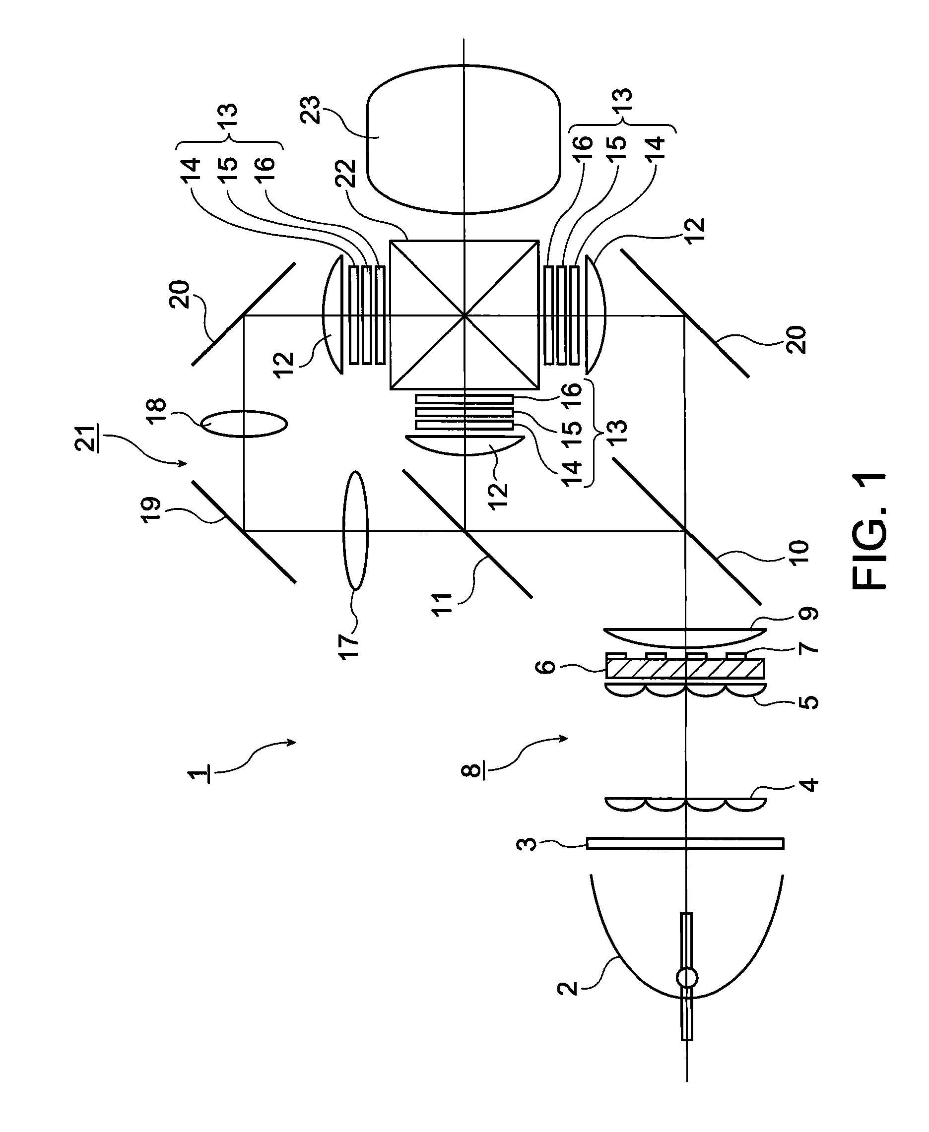
[0044]The present embodiment is an example of a so-called three-panel liquid crystal projector provided with a liquid crystal light valve for each of the colored light beams, a red light beam (R), a green light beam (G), and a blue light beam (B).

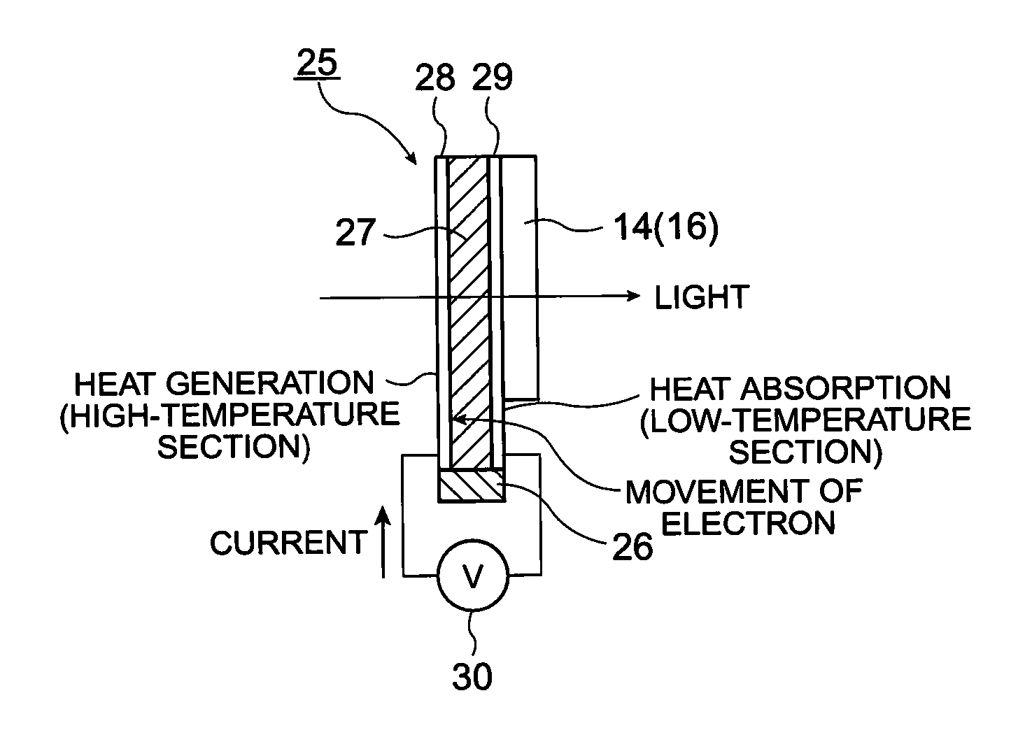
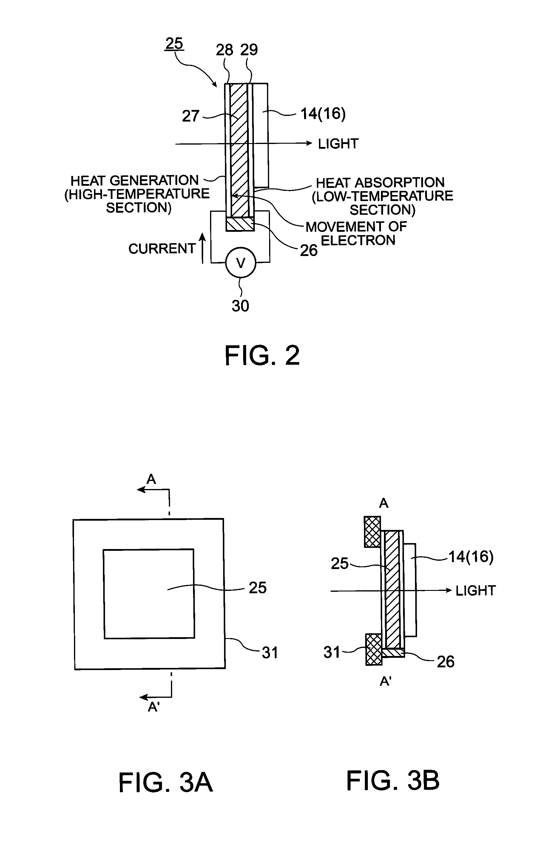
[0045]FIG. 1 is a schematic configuration diagram of the projector according to the present embodiment. FIGS. 2, 3A, and 3B are diagrams showing a usage configuration of a transparent thermoelectric conversion substrate used in the projector. It should be noted that in each of the drawings described below, the ratio, the scale size, and so on of each of the constituents are made different from each other in order for making the drawings eye-friendly.

[0046]In the projector 1 of the present embodiment, as shown in FIG. 1, a light source 2 is a high-intensity lamp such as a high-pressure mercury lamp, a xenon lamp, or a metal halid...

second embodiment

[0066]Hereinafter, a second embodiment of the invention will be explained with reference to FIG. 4.

[0067]The fundamental configuration of the projector of the present embodiment is the same as that of the first embodiment, and the only difference is the usage configuration of the transparent thermoelectric conversion substrate. The present embodiment also shows an example of the structure for cooling the polarization plate.

[0068]FIG. 4 is a diagram showing a usage configuration of a transparent thermoelectric conversion substrate in the projector of the present embodiment.

[0069]In the present embodiment, as shown in FIG. 4, the configuration of holding the polarization plate 14, 16 (or the polarization body) between a pair of transparent thermoelectric conversion substrates 25a, 25b is described. In other words, the both sides (both of the light entrance surface side and the light exit surface side) of the polarization plate 14, 16 (or the polarization body) are provided with the tr...

third embodiment

[0071]Hereinafter, a third embodiment of the invention will be explained with reference to FIG. 5.

[0072]The fundamental configuration of the projector of the present embodiment is the same as that of the first embodiment, and the only difference is the usage configuration of the transparent thermoelectric conversion substrate. The present embodiment also shows an example of the structure for cooling the polarization plate.

[0073]FIG. 5 is a diagram showing a usage configuration of a transparent thermoelectric conversion substrate in the projector of the present embodiment.

[0074]In the present embodiment, as shown in FIG. 5, there is described the configuration of the case in which the polarization plates 14, 16 respectively provided with the transparent thermoelectric conversion substrates 25a, 25b are used while being disposed in front of and behind the liquid crystal light valve 15. In this case, each of the polarization plates 14, 16 is preferably disposed with a slight gap (e.g.,...


PUM


Abstract

A projector includes a transmissive heat exchange element having a transparent thermoelectric conversion layer consisting mainly of an oxide and an electrode for supplying the transparent thermoelectric conversion layer with a current, and an optical element, and cooling or heating of the optical element is performed using the transmissive heat exchange element.

Description

BACKGROUND[0001]1. Technical Field[0002]The present invention relates to a projector and a display device, and in particular to a projector and a display device each having a temperature control structure with good efficiency of an optical element and being superior in thermal reliability.[0003]2. Related Art[0004]A projector in which a liquid crystal light valve is irradiated with light from a light source such as a high pressure mercury lamp or xenon lamp, and an image formed on the liquid crystal valve is enlargedly displayed on a screen by a projection lens or the like has been put into practice. While increase in brightness of the display image, namely increase in output of the light source, is in progress in order for making a projection image be viewed on a large screen even in a bright room, downsizing of the projector and the liquid crystal light valve is also in progress in order for making it easy to transport and handle the projector device. Therefore, the light with ext...

Claims


Application Information

Patent Timeline
Patent Type & Authority Patents(United States)
IPC IPC(8): G03B21/16
CPCG02F1/133385G03B21/16H01L35/22H04N9/3105H04N9/3144H04N9/3197G02F1/133528H10N10/855
Inventor ITO, YOSHITAKA
Owner SEIKO EPSON CORP
Learn More