Receiver
a receiver and receiver technology, applied in the field of receivers, can solve the problems of cost reduction, requirement is an obstacle to further downsizing, etc., and achieve the effect of cost reduction
- Summary
- Abstract
- Description
- Claims
- Application Information
AI Technical Summary
Benefits of technology
Problems solved by technology
Method used
Image
Examples
embodiment 1
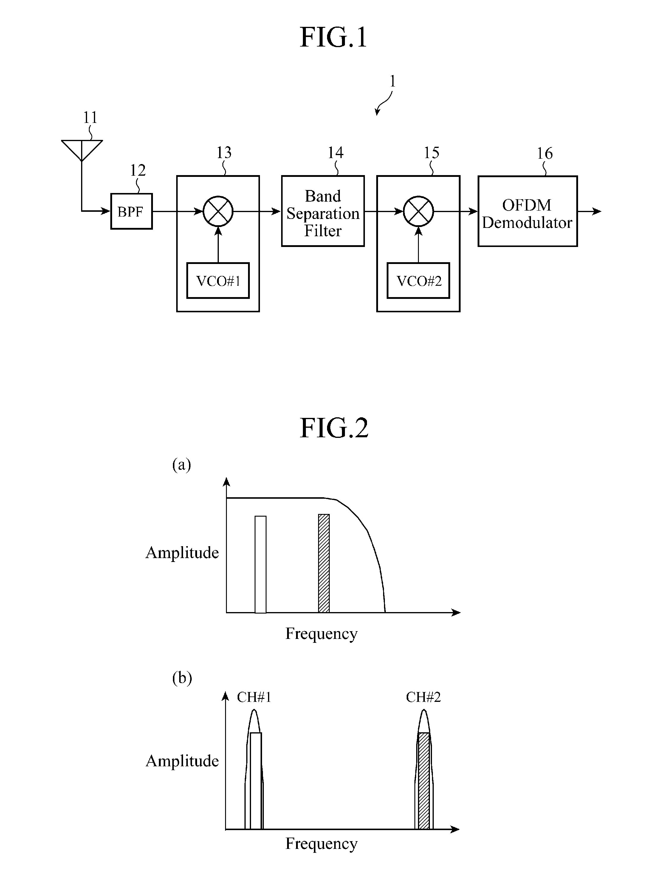
[0017]FIG. 1 is a block diagram showing the structure of a receiver in accordance with Embodiment 1 of the present invention. In this figure, a front end which outputs two or more broadcast waves (channels) on which the receiver has performed multichannel reception to an OFDM demodulator 16 is extracted and shown.
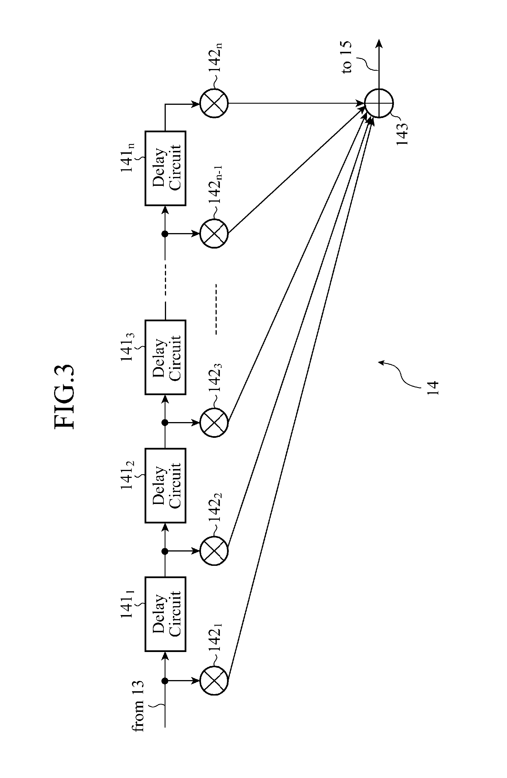
[0018]As shown in FIG. 1, the receiver 1 in accordance with Embodiment 1 of the present invention is comprised of an antenna 11, a band limiting filter (BPF) 12, a first frequency changing circuit 13, a band separation filter 14, a second frequency changing circuit 15, and the OFDM (Orthogonal Frequency Division Multiplex) demodulator 16.
[0019]In the above-mentioned structure, a received signal inputted via the antenna 11 is limited to an entire broadcast wave band (for example, a UHF (Ultra High Frequency) band) by the BPF 12.
[0020]The received signal limited by this BPF is mixed with a signal having a local frequency generated by a voltage controlled oscillator VCO (Volta...
embodiment 2
[0039]A receiver 1 in accordance with Embodiment 2, which will be explained hereafter, has the same structure as that in accordance with Embodiment 1 shown in FIG. 1. Therefore, the explanation of the structure of the receiver 1 in accordance with Embodiment 2 will be omitted to avoid a duplicated explanation. The receiver 1 in accordance with Embodiment 2 differs from that in accordance with Embodiment 1 in that an offset frequency fy is set to be equal to an integral multiple (n times) of the channel band fch of broadcast waves when an oscillating frequency fx provided to a VCO #1 of a first frequency changing circuit 13 is given by fx=½(f1+f2+fy). That is, fx is set to ½(f1+f2+fch×n).
[0040]The receiver in accordance with above-mentioned Embodiment 2 can set up an appropriate guard band (an available frequency region between adjacent channels) also at an intermediate frequency by setting the offset frequency fy to be equal to an integral multiple of the channel band fch of broadca...
embodiment 3
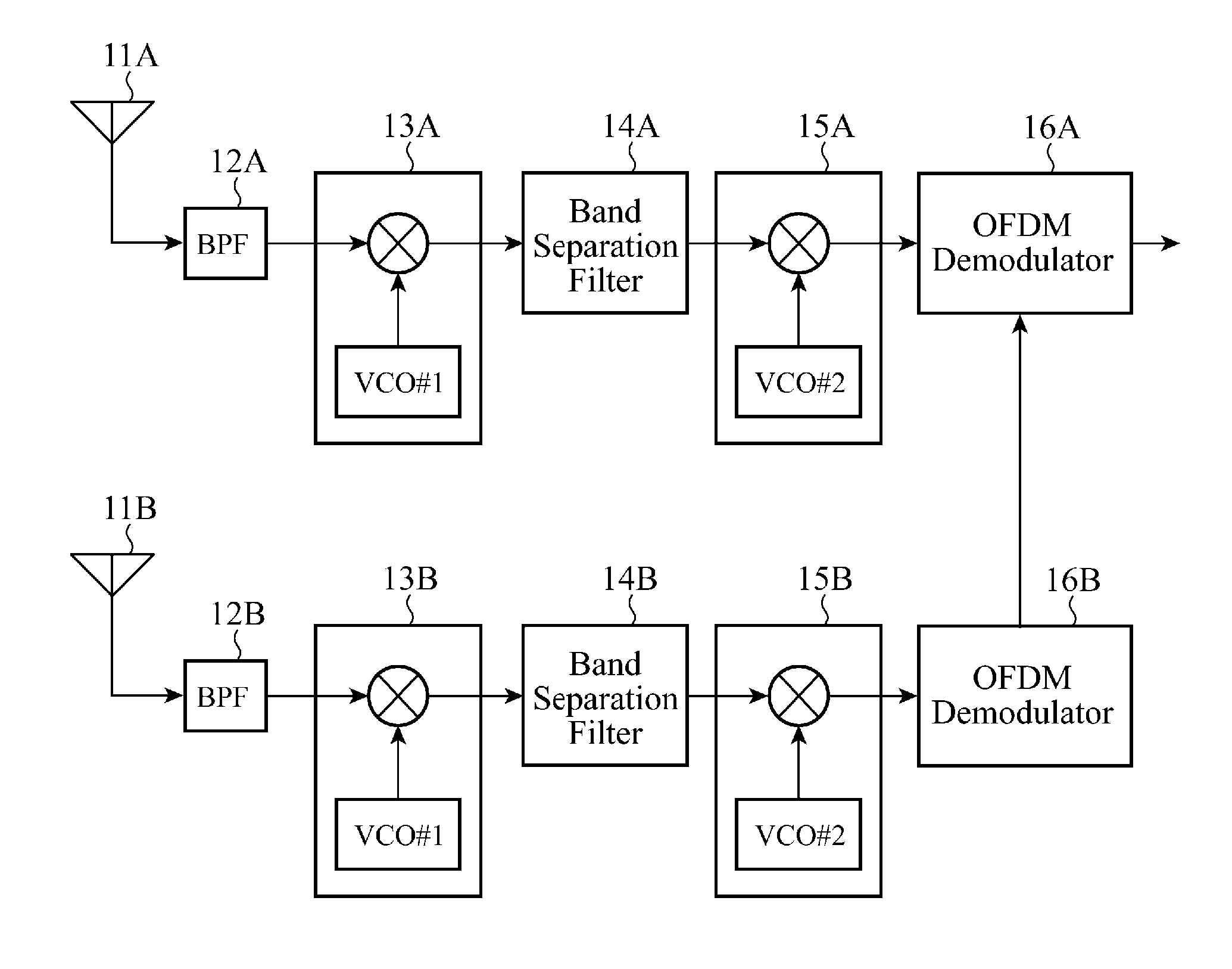
[0041]FIG. 5 is a block diagram showing the structure of a receiver in accordance with Embodiment 3 of the present invention, and shows an n-branch diversity receiver for combining two or more radio waves which the diversity receiver desires to receive or switching between them to take measures against fading by using n receivers 1 (n is a positive integer) each of which is comprised of an antenna 11, a BPF 12, a first frequency changing circuit 13, a band separation filter 14, a second frequency changing circuit 15, and an OFDM demodulator circuit 16, which are shown in FIG. 1.
[0042]In this embodiment, the diversity receiver has two receivers: a receiver 1A comprised of an antenna 11A, a BPF 12A, a first frequency changing circuit 13A, a band separation filter 14A, a second frequency changing circuit 15A and an OFDM demodulator 16A, and a receiver 1B comprised of an antenna 11B, a BPF 12B, a first frequency changing circuit 13B, a band separation filter 14B, a second frequency chan...
PUM
 Abstract
Description
Claims
Application Information
 - R&D
- Intellectual Property
- Life Sciences
- Materials
- Tech Scout
- Unparalleled Data Quality
- Higher Quality Content
- 60% Fewer Hallucinations
Browse by: Latest US Patents, China's latest patents, Technical Efficacy Thesaurus, Application Domain, Technology Topic, Popular Technical Reports.
© 2025 PatSnap. All rights reserved.Legal|Privacy policy|Modern Slavery Act Transparency Statement|Sitemap|About US| Contact US: help@patsnap.com


