Receiver

a receiver and receiver technology, applied in the field of receivers, can solve the problems of requiring further downsizing and cost reduction, and achieve the effect of cost reduction

Inactive Publication Date: 2011-10-06
MITSUBISHI ELECTRIC CORP
View PDF7 Cites 0 Cited by
  • Summary
  • Abstract
  • Description
  • Claims
  • Application Information

AI Technical Summary

Benefits of technology

[0010]Therefore, the receiver in accordance with the present invention makes it possible to...

Problems solved by technology

Therefore, this requirement is an obstacle ...

Method used


Image

  • Receiver
  • Receiver
  • Receiver

Examples


embodiment 1

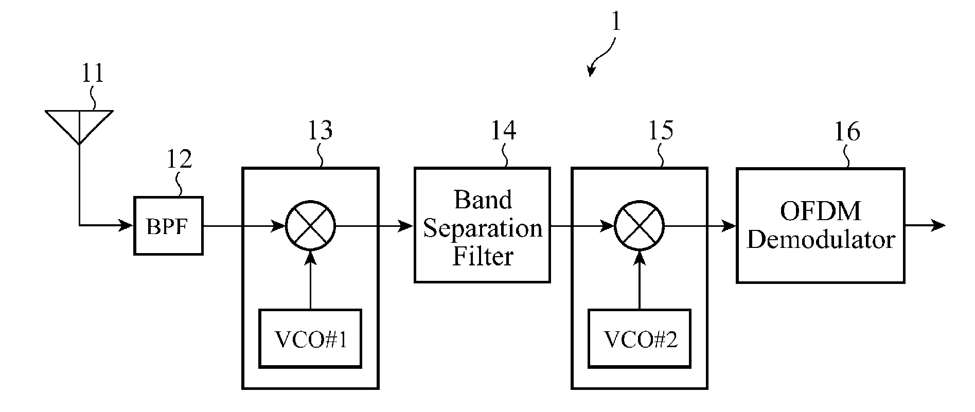
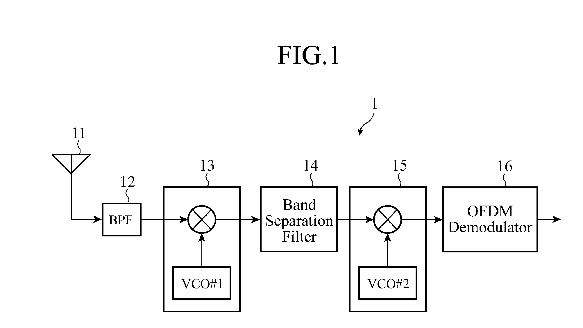
[0025]FIG. 1 is a block diagram showing the structure of a receiver in accordance with Embodiment 1 of the present invention. As shown in FIG. 1, the receiver 1 in accordance with Embodiment 1 of the present invention is comprised of an antenna 11, a band limiting filter (BPF) 12, a first frequency changing circuit 13, a band separation filter 14, a second frequency changing circuit 15, and an OFDM (Orthogonal Frequency Division Multiplex) demodulator 16.

[0026]In this embodiment, only an LSI structure of a receiving system except the antenna 11 is shown, and an LSI structure of a playback system including a decoding circuit and a DA conversion circuit which are connected downstream from the OFDM demodulator 16 are not shown.

[0027]In the above-mentioned structure, a received signal inputted via the antenna 11 is limited to an entire broadcast wave band (for example, a UHF (Ultra High Frequency) band) by the BPF 12. The received signal limited by this BPF is mixed with a signal having...

embodiment 2

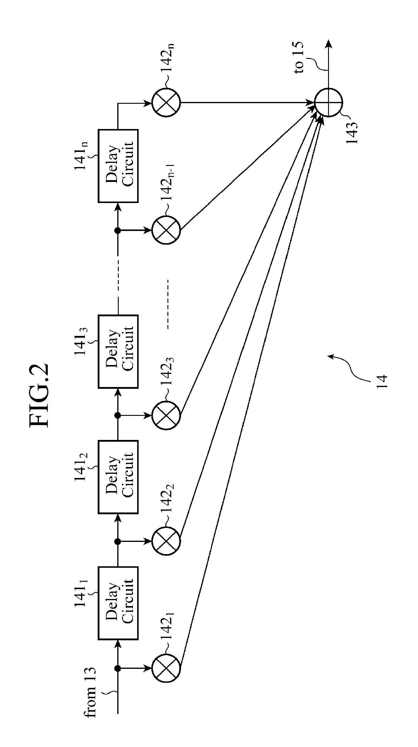
[0047]FIGS. 6 and 7 are block diagrams showing the structure of a band separation filter 14 for use in a receiver 1 in accordance with Embodiment 2 of the present invention. In this embodiment, only a coefficient generating unit of an FIR type filter shown as Embodiment 1 in FIG. 2 is extracted and shown.

[0048]In FIGS. 6 and 7, because a part of delay circuits 1411 to 141n and a part of coefficient multiplying units 1421 to 142n have the same structure as those shown in FIG. 2, respectively, and the parts are not shown.

[0049]The coefficient generating unit of the FIR type filter which constructs the band separation filter 14 calculates coefficients by using an arithmetic operation of a coefficient calculating circuit 144, as shown in FIG. 6(a). As an alternative, as shown in FIG. 6(b), the coefficient generating unit of the FIR type filter which constructs the band separation filter 14 is comprised of a coefficient table 145 in which combinations of some coefficients are stored in a...

embodiment 3

[0053]FIG. 8 is a block diagram showing the structure of a band separation filter for use in a receiver in accordance with Embodiment 3 of the present invention. The band separation filter in accordance with Embodiment 3 has a structure of including a broadcast wave arrangement detecting unit 148 and a table update control unit 149 in addition to the structure in accordance with Embodiment 2 shown in FIG. 6(b).

[0054]The broadcast wave arrangement detecting unit 148 detects a broadcast wave arrangement, and the table update control unit 149 calculates a filter characteristic according to the broadcast wave arrangement detected by the broadcast wave arrangement detecting unit 148 and generates new FIR filter coefficients to update table data stored in a coefficient table 145.

[0055]It is assumed that the broadcast wave arrangement detecting unit 148 uses a method of carrying out normal channel scanning, and updating the broadcast wave arrangement which the broadcast wave arrangement de...


PUM


Abstract

A receiver 1 is comprised of a first frequency changing circuit 13 for converting a received signal including two or more broadcast waves into a first intermediate frequency signal with a local oscillation, a band separation filter 14 consisting of a multistage FIR type filter for allowing bands included in the two or more broadcast waves converted into the above-mentioned first intermediate frequency signal to pass therethrough simultaneously, and a second frequency changing circuit 15 for converting the received signal which is outputted by the above-mentioned band separation filter 14 and which is limited to the above-mentioned two or more broadcast waves which the receiver desires to receive into a second intermediate frequency signal from which each of the broadcast waves can be sampled at a frequency at which the broadcast waves do not interfere with one another.

Description

FIELD OF THE INVENTION[0001]The present invention relates to a receiver capable of receiving multiple channels which simultaneously receives two or more broadcast waves.BACKGROUND OF THE INVENTION[0002]Many patent applications about a technology regarding a multichannel receiver that receives two or more broadcast waves simultaneously, for providing a receiver having a low-cost structure by sharing components among different models to reduce the component count have been applied.[0003]For example, a multichannel receiver which has a frequency changing circuit for splitting one antenna input and then converting each broadcast wave which the multichannel receiver desires to receive into a signal having an intermediate frequency, and a band limiting filter, and which reduces its components, such as the antenna, by outputting one or more tuner outputs and performing signal demodulation on each of the one or more tuner outputs is known (for example, refer to patent reference 1).[0004]Fur...

Claims


Application Information

Patent Timeline
IPC IPC(8): H04B1/06
CPCH04B1/28H04L5/0005H04L5/0007H04B1/30H04L27/2334H04L27/2649H04L27/28H04L5/06
Inventor TAKEUCHI, MITSURUARITA, EIJI
Owner MITSUBISHI ELECTRIC CORP
Why Eureka
Try Eureka