
Suspension bicycle seat post

a bicycle seat post and handlebar technology, applied in the field of bicycles, can solve the problems of dampening the energy communicated to the frame of the bicycle, providing with fairly aggressive and complex shock or linkage systems, and outweighing perceived advantages, so as to achieve the effect of dampening movemen

Active Publication Date: 2011-10-25
TREK BICYCLE CORPORATION
View PDF40 Cites 11 Cited by
  • Summary
  • Abstract
  • Description
  • Claims
  • Application Information

AI Technical Summary

Benefits of technology

The present invention provides a suspension bicycle seat post assembly that dampens movement between a seat and a bicycle frame. The assembly includes a seat post, a collar, a dampener, and a hinge. The collar is pivotably connected to the seat post and can rotate relative to the seat. The dampener is positioned between the collar and the seat post and dampens movement of the bicycle seat relative to the bicycle frame. The hinge connects the collar and the stem and allows the seat to rotate about the hinge. The invention also includes a method of dampening motion between the seat and frame. The technical effects of the invention include reducing side-to-side motion of the seat, improving stability, and enhancing comfort for the rider.

Problems solved by technology

Many bicycles intended for off-road use are provided with fairly aggressive and complex shock or linkage systems that accommodate vertical movement of the front wheel and / or the rear wheel with respect to the bicycle frame.
Although such systems dampen energy communicated to the frame of the bicycle, such systems do little to dampen vibration between the frame and the structures that interact with the rider, such as the handlebars or the seat.
Many such configurations have drawbacks that outweigh their perceived advantages.
Such systems are only capable of dampening vibrations associated with the seat post and do not accommodate dampening of impact shocks that can occur between the seat or handlebars and the frame as the wheels encounter more than inconsequential discontinuities along the ground surface.
Unfortunately, such systems are also not without their respective drawbacks.
Although such systems isolate the seat from frame vibrations, the omni-directional instability of the vibration isolation system detracts from the ability of a rider to interact with the bicycle frame in a manner in which they are accustomed.

Method used


Image

  • Suspension bicycle seat post
  • Suspension bicycle seat post
  • Suspension bicycle seat post

Examples


Embodiment Construction

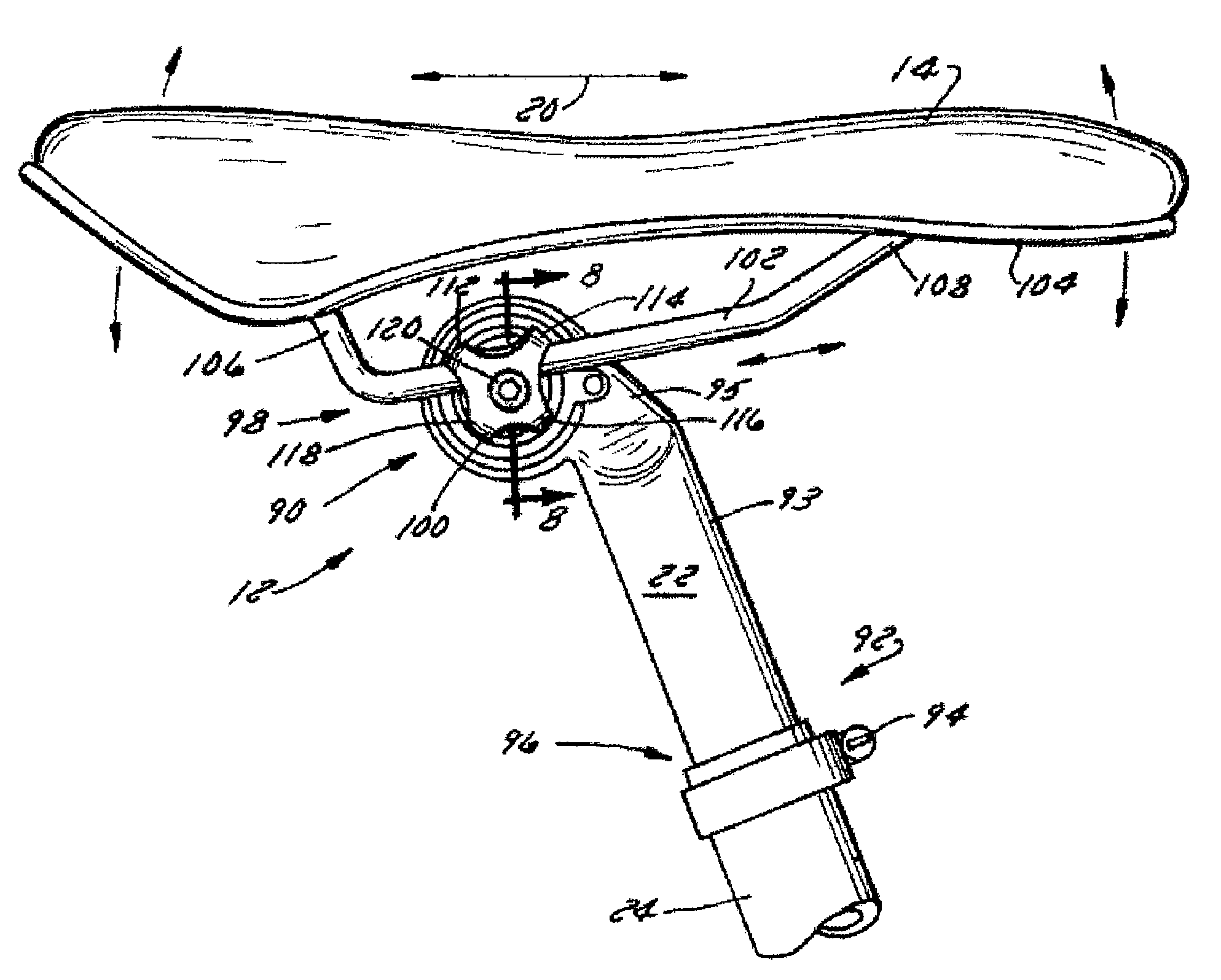
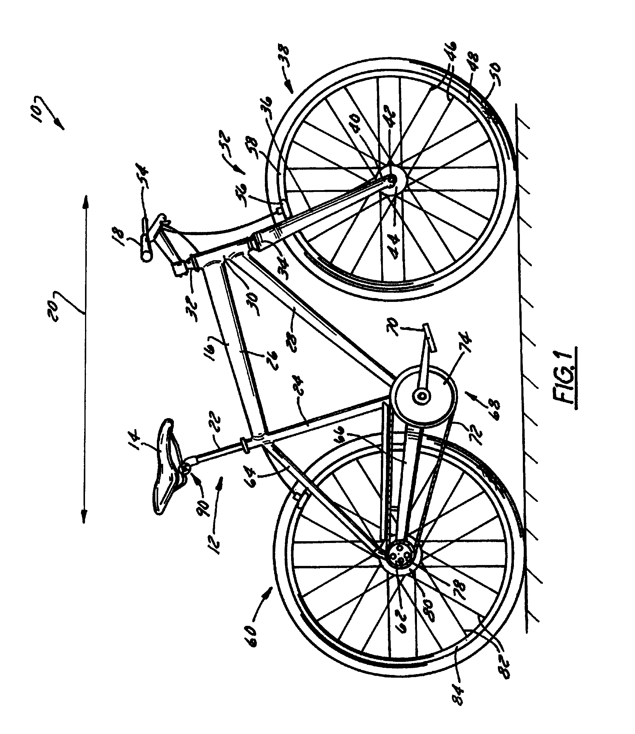
[0024]FIG. 1 shows a bicycle 10 having a seat post assembly 12 that is constructed according to the present invention. Seat post assembly 12 attaches a seat 14 to a frame 16 of bicycle 10. Handlebars 18 are attached to frame 16 generally forward of seat 14 with respect to a longitudinal axis, indicated by arrow 20, of bicycle 10. Seat post assembly 12 includes a seat post 22 that slidably or telescopically engages a seat tube 24 of frame 16. Frame 16 includes a top tube 26 and a down tube 28 that extend forwardly from seat tube 24 to a head tube 30 that connects the generally forward ends of top tube and down tube 26, 28.

[0025]Handlebars 18 are connected to a stem 32 that passes through head tube 30 and engages a fork crown 34. A pair of forks 36 extend from generally opposite ends of fork crown 34 and are constructed to support a front wheel assembly 38 at an end thereof or fork tip 40. Fork tips 40 engage generally opposite sides of an axle 42 that is constructed to engage a hub 4...


PUM


Abstract

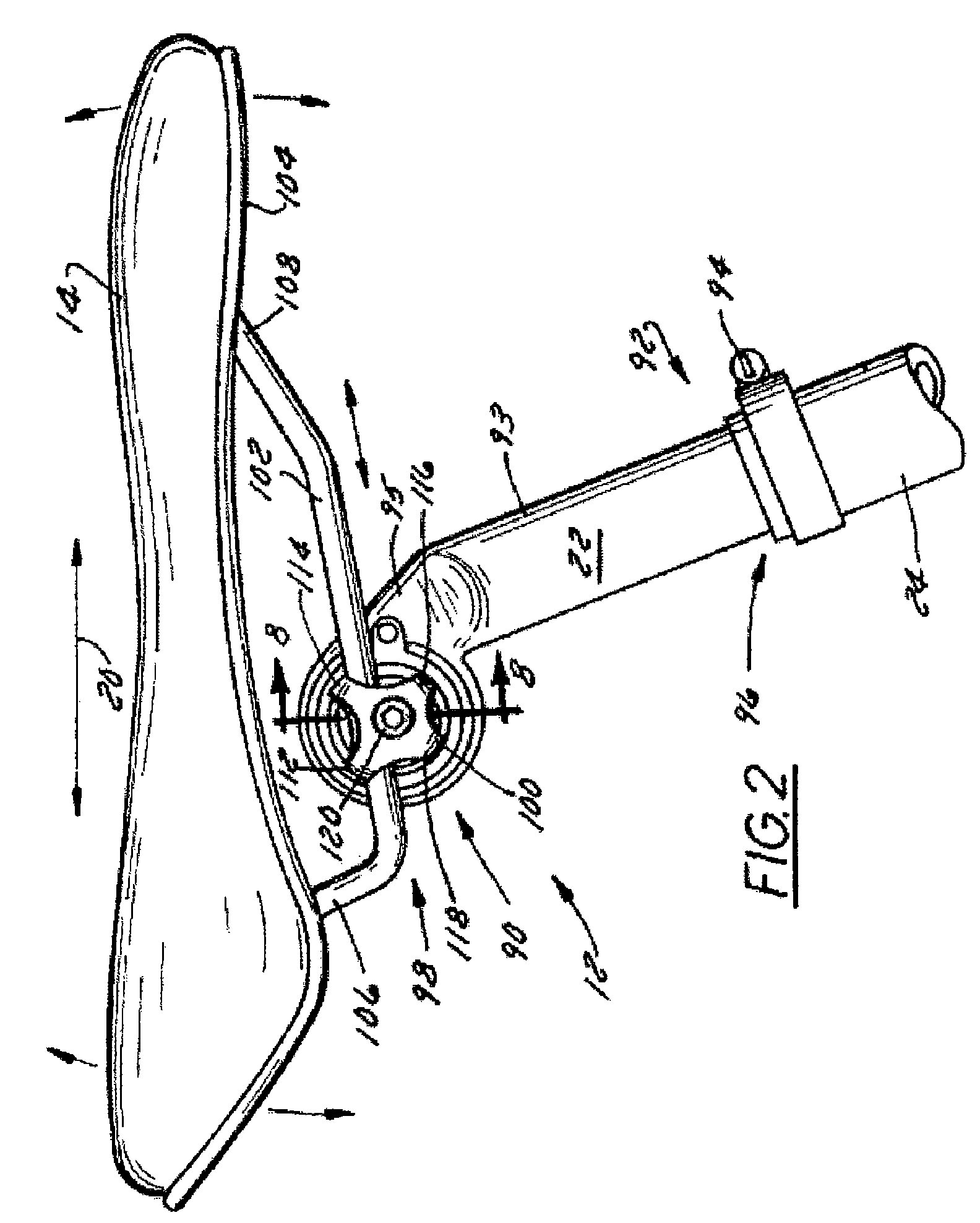
A bicycle seat post assembly that dampens movement between a seat and a bicycle frame. The seat post assembly includes a seat post, a collar that passes through the seat post, and a dampener that is disposed between the collar and the seat post. The collar is pivotably connected to the seat post so that the collar can rotate relative to the seat post. The collar rotates about an axis that extends in a crossing direction relative to both a longitudinal axis of the bicycle frame and a longitudinal axis of the seat post.

Description

BACKGROUND OF THE INVENTION[0001]The present invention relates generally to bicycles and, more particularly, to a bicycle seat post or handlebar suspension assembly that reduces shocks from being communicated between the bicycle frame and the rider.[0002]The primary structural component of a conventional two-wheel bicycle is the frame. Most bicycles are defined by a frame that is typically constructed from a set of tubular members that are connected together. For many bicycles, the frame is constructed from members commonly referred to as the top tube, down tube, seat tube, seat stays and chain stays, and those members are joined together at intersections commonly referred to as the head tube, seat post, bottom bracket and rear dropout. A front wheel and a rear wheel are generally attached at forward and rearward locations, respectively, with respect to frame. A handlebar and a seat extend in an upward direction from the frame at locations that are generally between the front and re...

Claims


Application Information

Patent Timeline
Patent Type & Authority Patents(United States)
IPC IPC(8): B62K19/36
CPCB62J1/04B62J1/08F16F1/3863B62K2201/02
Inventor CUSACK, DOUGLAS A.
Owner TREK BICYCLE CORPORATION
Learn More