Jump rope assembly having enhanced strength

Inactive Publication Date: 2011-10-25
EVER GYM ENTERPRISES
View PDF6 Cites 15 Cited by
  • Summary
  • Abstract
  • Description
  • Claims
  • Application Information

AI Technical Summary

Benefits of technology

According to the primary advantage of the present invention, the rope body is fixed between the fixing plug and the retaining ring, and the retaining ring is located between the catch portion and the conical portion of the fixing plug and is moved to abut the stop flange of the connecting sleeve, so that the rope body is locked onto the connecting sleeve by the fixing plug and the retaining ring, and is combined with the connecting unit solidly and stably.
According to another advantage of the present invention, the enlarged end portion of the handle is pivoted in the receiving space of the connecting sleeve by guidance of the semi-spherical surface, so that the handle unit is pivoted universally relative to the connecting unit to faci

Problems solved by technology

However, when an external force applied on the rope body 40 is greater than a connecting force between the hooked portions 521 of the plu

Method used


Image

  • Jump rope assembly having enhanced strength
  • Jump rope assembly having enhanced strength
  • Jump rope assembly having enhanced strength

Examples


Embodiment Construction

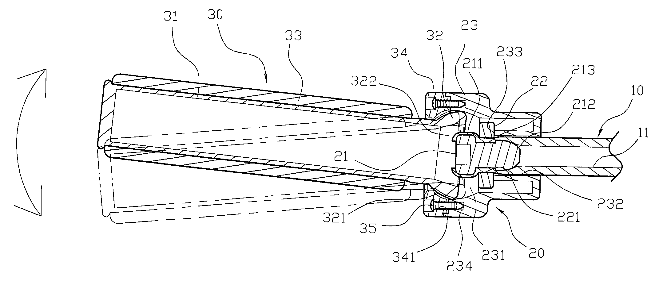
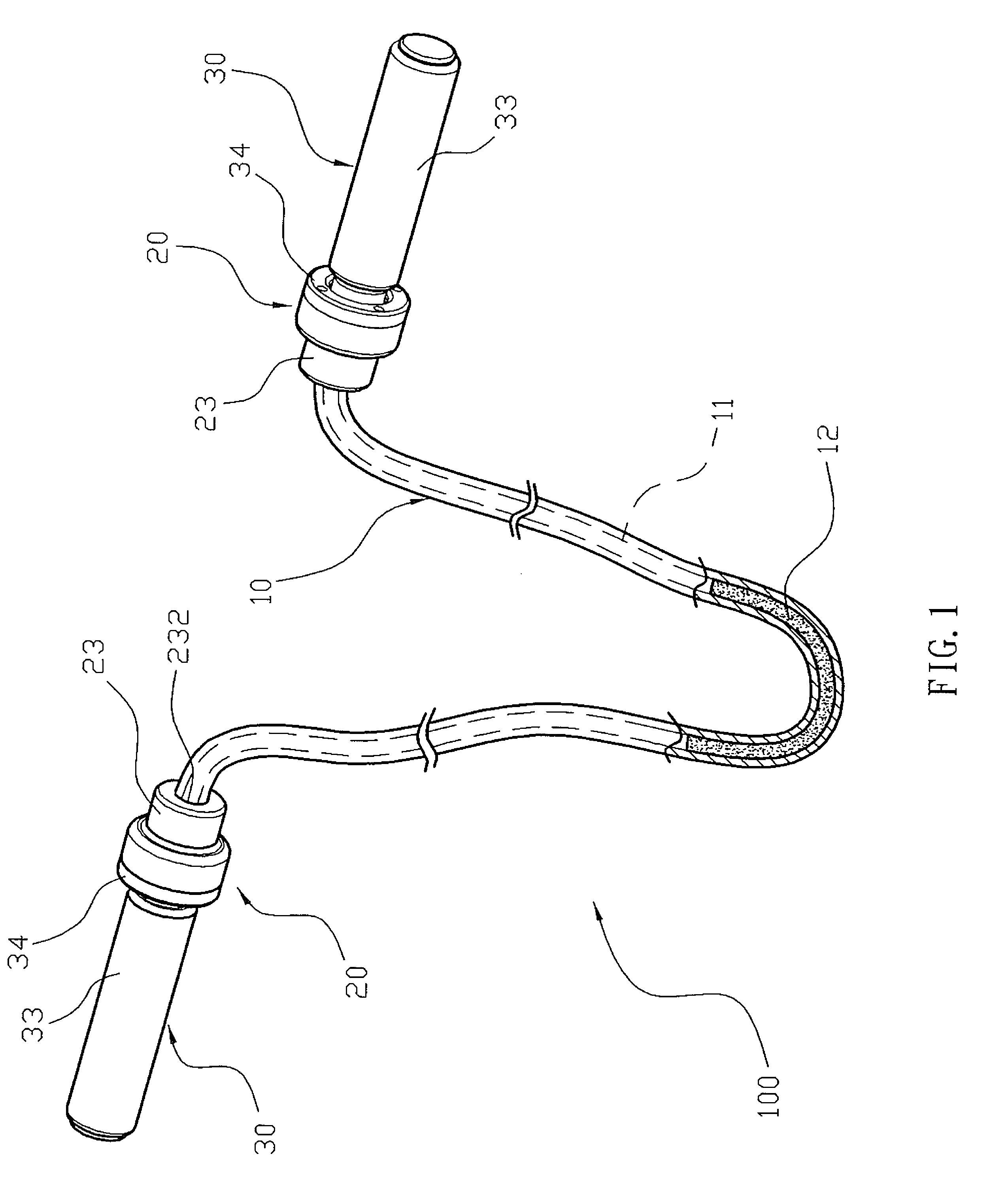
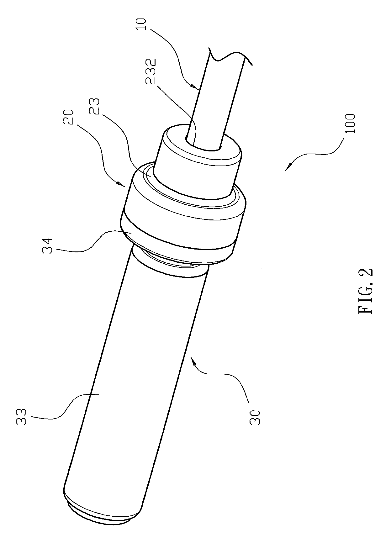
Referring to the drawings and initially to FIGS. 1-6, a jump rope assembly 100 in accordance with the preferred embodiment of the present invention comprises a rope body 10 having two opposite ends each connected with a connecting unit 20 and a handle unit 30.

The rope body 10 has a hollow inner portion provided with a through hole 11. The through hole 11 of the rope body 10 contains a filling member 12 to increase the weight of the rope body 10. Preferably, the filling member 12 contains particles, such as sand particles, plastic particles, steel balls and the like. Alternatively, the filling member 12 contains fluid, such as water, oil and the like.

The connecting unit 20 includes a connecting sleeve 23 mounted on the rope body 10, a fixing plug 21 inserted into the through hole 11 of the rope body 10, and a retaining ring 22 mounted in the connecting sleeve 23 and compressing the rope body 10 to press the rope body 10 toward the fixing plug 21 so that the rope body 10 is fixed betw...


PUM


Abstract

A jump rope assembly includes a rope body having two ends each connected with a connecting unit and a handle unit. The rope body has an inner portion provided with a through hole. The connecting unit includes a connecting sleeve mounted on the rope body, a fixing plug inserted into the through hole of the rope body, and a retaining ring mounted in the connecting sleeve and compressing the rope body to press the rope body toward the fixing plug so that the rope body is fixed between the fixing plug and the retaining ring. The handle unit includes a handle having an enlarged end portion mounted in the connecting sleeve, and a locking ring mounted on the enlarged end portion of the handle and locked onto the connecting sleeve.

Description

BACKGROUND OF THE INVENTION1. Field of the InventionThe present invention relates to a jumping device and, more particularly, to a jump rope assembly.2. Description of the Related ArtA conventional jump rope assembly in accordance with the prior art shown in FIGS. 8 and 9 comprises a rope body 40 having two opposite ends each connected with a connecting member 50, a first holding cover 60 and a second holding cover 70. The rope body 40 has a hollow inner portion provided with a through hole 41. The connecting member 50 has a first end provided with a catch portion 51 and a second end provided with a plug 52 which has multiple hooked portions 521. The plug 52 of the connecting member 50 is inserted into the through hole 41 of the rope body 40 until the catch portion 51 of the connecting member 50 abuts the rope body 40 so that the connecting member 50 is locked onto the rope body 40 by the hooked portions 521 of the plug 52. The first holding cover 60 is combined with the second hold...

Claims


Application Information

Patent Timeline
IPC IPC(8): A63B21/00
CPCA63B5/20
Inventor CHEN, MING-CHIN
Owner EVER GYM ENTERPRISES
Why Eureka
Try Eureka