
Lens driving unit and camera module comprising the same

a technology of driving unit and camera module, which is applied in the direction of piezoelectric/electrostriction/magnetostriction machines, mountings, instruments, etc., can solve the problems of increasing the size of the operation module, increasing the manufacturing cost, and increasing the number of components, so as to achieve precise linear motion

Active Publication Date: 2011-11-01
HANWHA TECHWIN CO LTD
View PDF7 Cites 12 Cited by
  • Summary
  • Abstract
  • Description
  • Claims
  • Application Information

AI Technical Summary

Benefits of technology

The present invention provides a lens driving unit that generates a precise linear motion in a spatially limited structure using a bending vibration piezoelectric motor. This new structure allows for a means of supporting a lens and moving it along an axis perpendicular to the face of the lens with a bending motion. The lens driving unit includes a lens carrier with a guide axis, a piezoelectric driving unit with a center portion contacting the guide axis, and a driving unit holder supporting both ends of an elastic element. The elastic element is longer than the first piezoelectric element and a contacting unit is in contact with the guide axis. The lens driving unit also includes at least one side spring and a lower spring to provide a restoring force with regard to the bending motion of the piezoelectric element. The lens driving unit may also include a ball bearing and a ball groove guiding the lens carrier and a reflective plate detecting the movement of the lens carrier. The camera module includes a lens carrier with a guide axis, a piezoelectric driving unit with a center portion contacting the guide axis, and a module base supporting the lens carrier to allow it to move in at least one direction. The camera module may also include an extension wing extending from the exterior surface of the lens carrier, a reflective plate formed on the bottom surface of the extension wing, and a sensor detecting the movement of the lens carrier.

Problems solved by technology

However, the stepping motor needs a lot of components due to the sizes of a reduction gear, a connecting area, and itself, which may result in increasing the size of an operation module.
Also, the increase in the number of components may increase manufacturing cost.

Method used


Image

  • Lens driving unit and camera module comprising the same
  • Lens driving unit and camera module comprising the same
  • Lens driving unit and camera module comprising the same

Examples


Embodiment Construction

Hereinafter, the present invention will be described in detail by explaining exemplary embodiments of the invention with reference to the attached drawings.

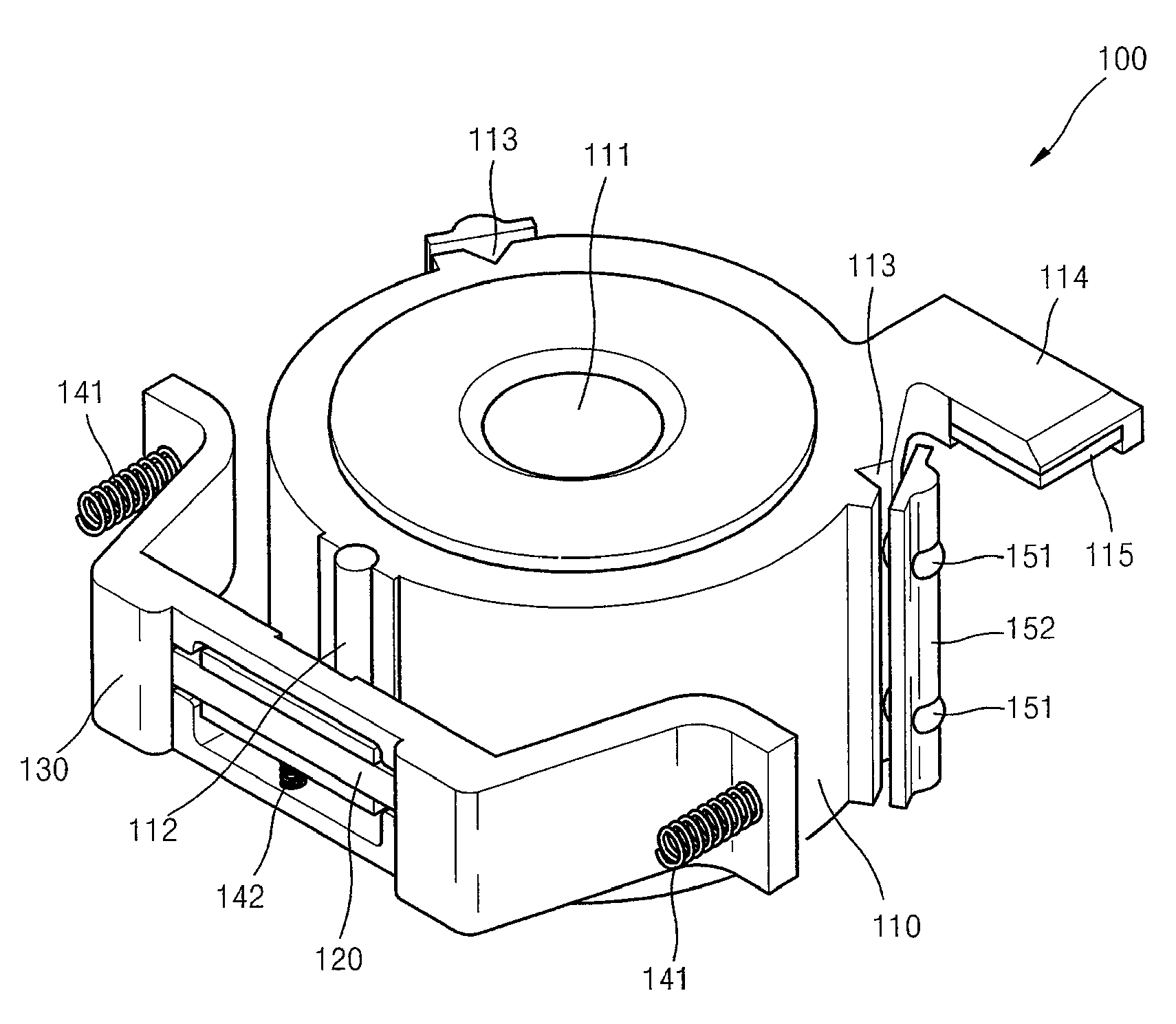
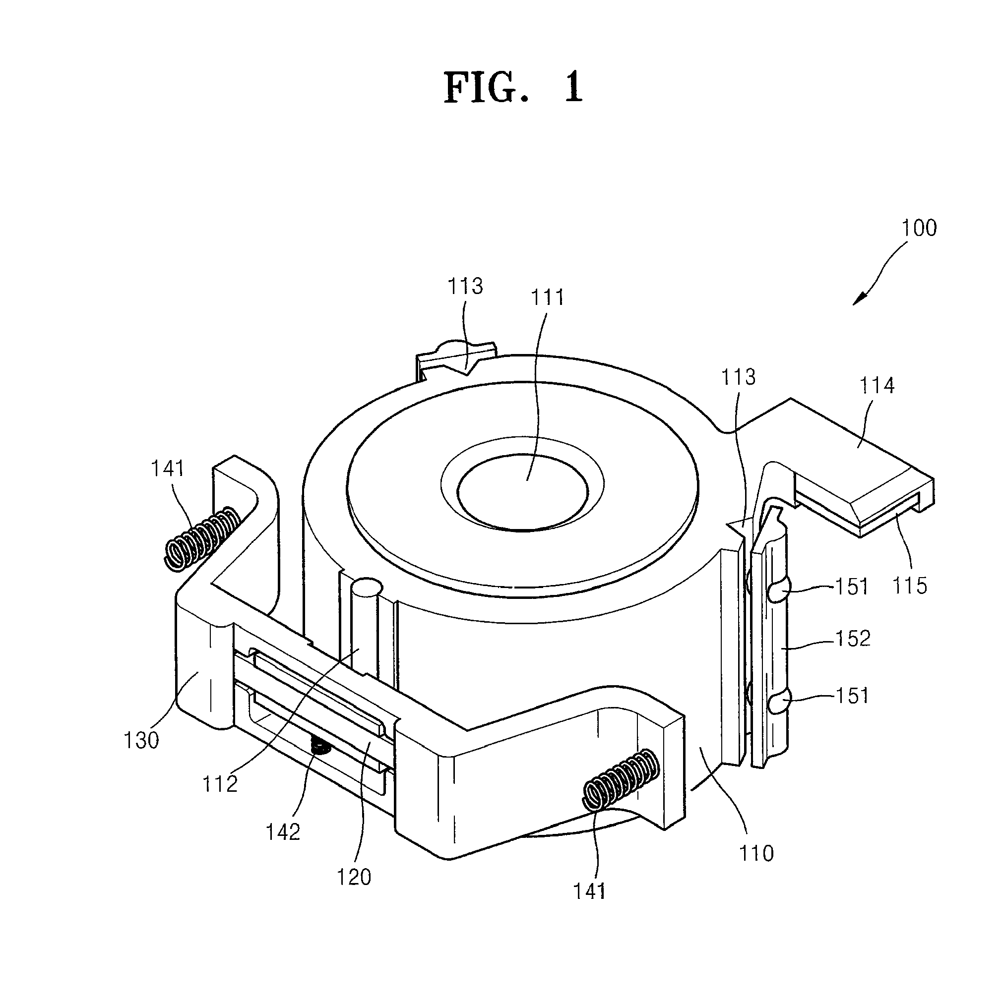
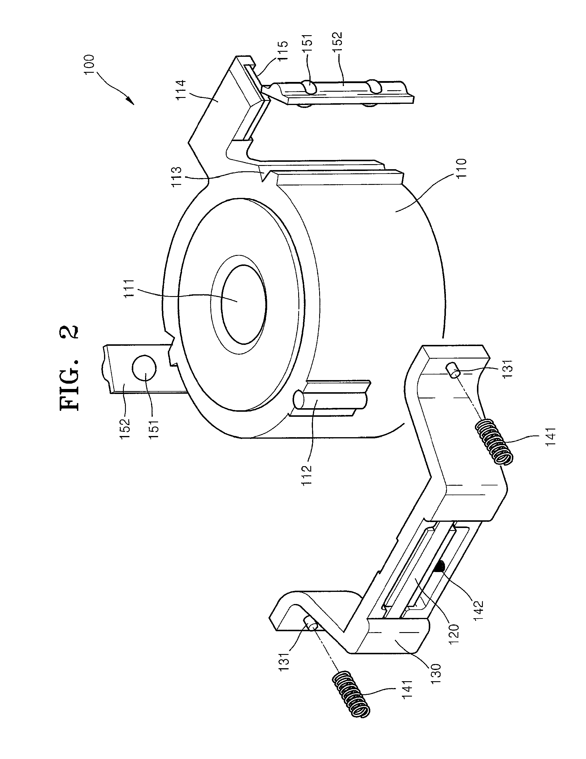
FIG. 1 is a perspective view of a lens driving unit 100 according to an embodiment of the present invention. FIG. 2 is an exploded perspective view of the lens driving unit 100 shown in FIG. 1, according to an embodiment of the present invention. FIG. 3 is a perspective view of a piezoelectric driving unit 120 of the lens driving unit 100 shown in FIG. 1, according to an embodiment of the present invention.

Referring to FIGS. 1 through 3, the lens driving unit 100 may comprise a lens carrier 110 and the piezoelectric driving unit 120.

The lens carrier 110 for supporting a lens 111 inside thereof may comprise a guide axis 112. The guide axis 112 may be at least partially exposed to the outside and extend in a direction substantially perpendicular to the lens 111.

The guide axis 112 may be integrally attached to or disposed in the len...


PUM


Abstract

Provided are a lens driving unit that generates a precise linear motion in a spatially limited structure by using a bending vibration piezoelectric motor having a new structure, and a camera module comprising the lens driving unit. The lens driving unit includes: a lens carrier supporting a lens and comprising a guide axis exposed at least partially to the outside and extending in a direction substantially perpendicular to the lens; and a piezoelectric driving unit having a center portion contacting the guide axis according to a bending motion of a piezoelectric element and moving the lens carrier in a direction in which the guide axis extends.

Description

CROSS-REFERENCE TO RELATED PATENT APPLICATIONThis application claims the benefit of Korean Patent Application No. 10-2008-0101128, filed on Oct. 15, 2008, in the Korean Intellectual Property Office, the disclosures of which are incorporated herein in their entirety by reference.BACKGROUND OF THE INVENTION1. Field of the InventionThe present invention relates to a lens driving unit and a camera module comprising the same, and more particularly, to a lens driving unit that generates a precise linear motion in a spatially limited structure by using a bending vibration piezoelectric motor so as to perform an auto-focusing (AF) function or a zooming function, and a camera module comprising the lens driving unit.2. Description of the Related ArtRecently portable electronic devices have increasingly employed a camera module having an auto-focusing (AF) function or a zooming function. Cellular phones employ small and thin camera modules since the thicker the camera modules are, the thicker ...

Claims


Application Information

Patent Timeline
Patent Type & Authority Patents(United States)
IPC IPC(8): G02B15/14
CPCG02B7/08G02B13/001H02N2/025H04N23/00
Inventor JUNG, TAE-HOONKIM, DAE-KYUNGLEE, IN-HWAN
Owner HANWHA TECHWIN CO LTD
Learn More