Method for power management for computer system

a technology for computer systems and power management, applied in the field of computer systems, can solve problems such as the inability of computer systems to opera

Active Publication Date: 2011-11-01
VIA TECH INC
View PDF3 Cites 8 Cited by
  • Summary
  • Abstract
  • Description
  • Claims
  • Application Information

AI Technical Summary

Problems solved by technology

Because a battery has a limited amount of power, a computer system cannot operate when the power of the battery is exhausted.

Method used


Image

  • Method for power management for computer system
  • Method for power management for computer system
  • Method for power management for computer system

Examples


Embodiment Construction

[0019]The following description is of the best-contemplated mode of carrying out the invention. This description is made for the purpose of illustrating the general principles of the invention and should not be taken in a limiting sense. The scope of the invention is best determined by reference to the appended claims.

[0020]Referring to FIG. 3, a block diagram of a computer system 300 with a battery 308 as a power supply according to the invention is shown. The computer system 300 may be a handheld device or a notebook, for example. In one embodiment, the computer system 300 comprises a system controller 302, a chipset 304, a system management bus 310, the battery 308, and other device 312. The system controller 302 is a core of the computer system 300 and controls other component devices of the computer system 300. In one embodiment, the system controller 302 can be a central processor unit (CPU). The battery 308 provides power for operating all the component devices of the compute...


PUM


Abstract

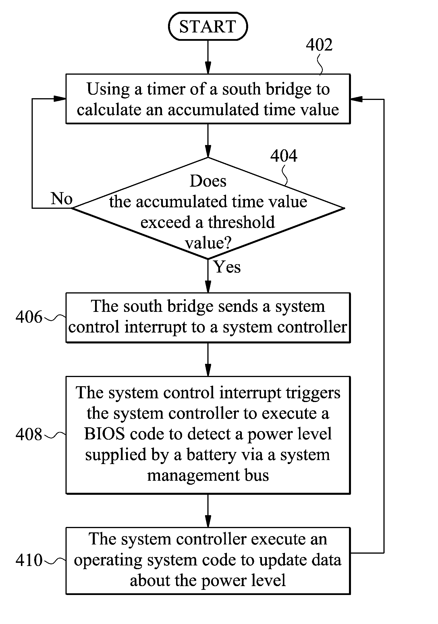
The invention provides a method for power management for a computer system. In one embodiment, the computer system comprises a system controller, a chipset, and a battery coupled to the chipset via a system management bus. First, a timer of the chipset is used to calculate an accumulated time value. When the accumulated time value exceeds a threshold value, the chipset is directed to send a system control interrupt to the system controller. After the system controller receives the system control interrupt, the system controller is triggered to detect a power level supplied by the battery via the system management bus.

Description

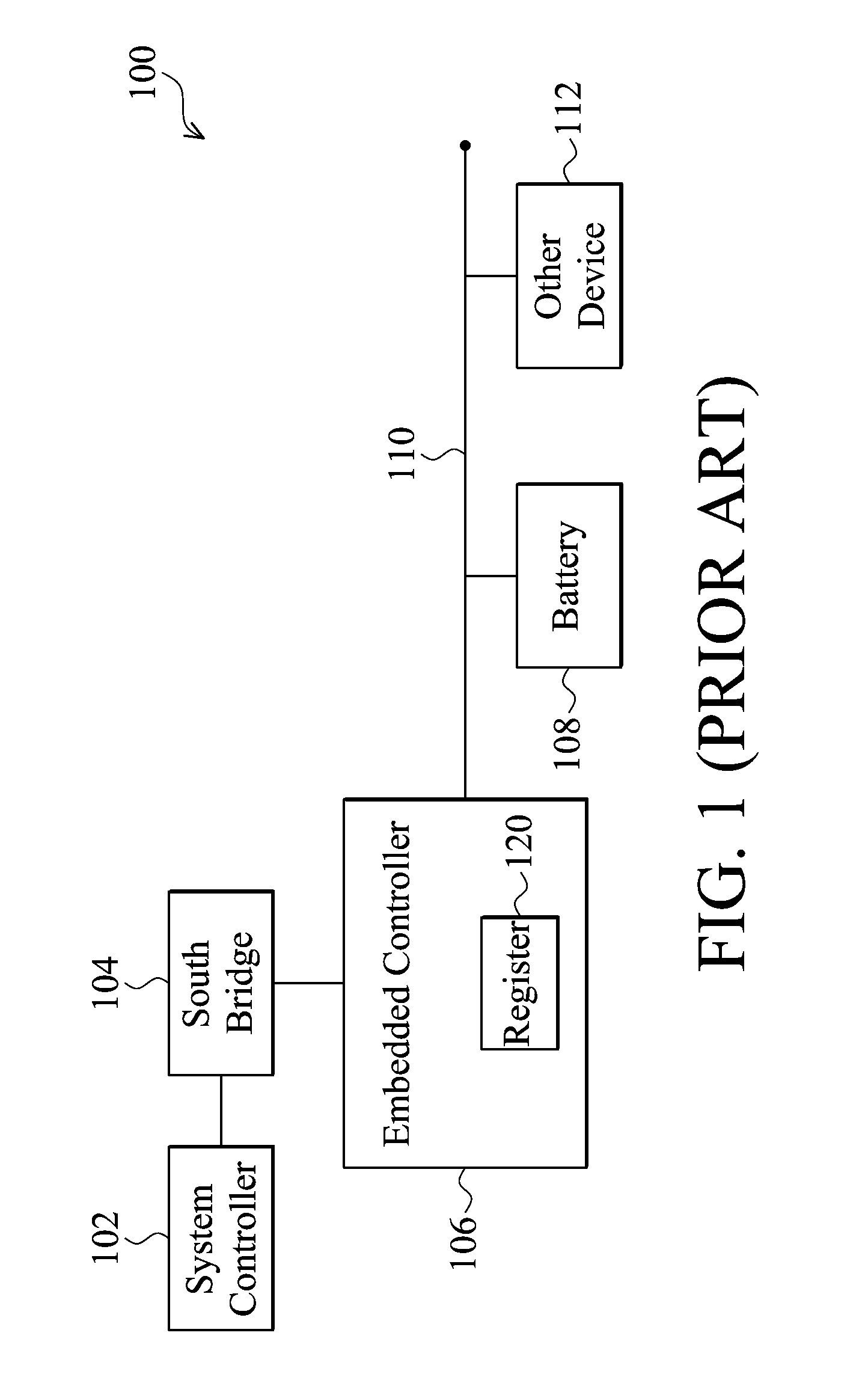
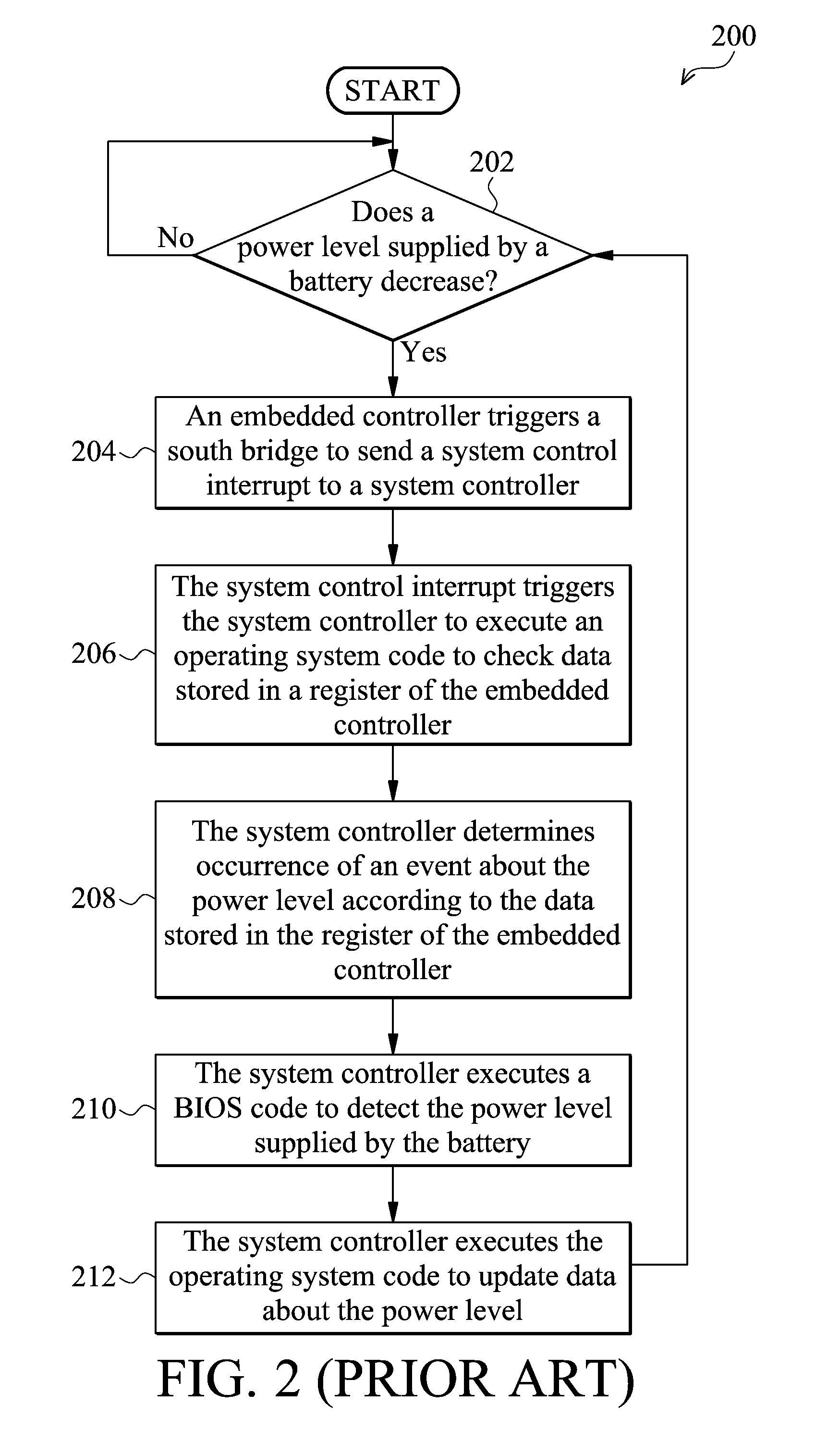
CROSS REFERENCE TO RELATED APPLICATIONS[0001]This Application claims priority of Taiwan Patent Application No. TW97111970, filed on Apr. 2, 2008, the entirety of which is incorporated by reference herein.BACKGROUND OF THE INVENTION[0002]1. Field of the Invention[0003]The invention relates to computer systems, and more particularly to power management for computer systems.[0004]2. Description of the Related Art[0005]A computer system, such as a handheld device or a notebook, operates according to power supplied by batteries. Because a battery has a limited amount of power, a computer system cannot operate when the power of the battery is exhausted. The computer system therefore must know a power level of the battery. When the power level of the battery is lower than a threshold value, the computer system must remind a user of the reduced power level, thus directing the user to replace the battery with a new one.[0006]Referring to FIG. 1, a block diagram of a conventional computer sys...

Claims


Application Information

Patent Timeline
Patent Type & Authority Patents(United States)
IPC IPC(8): G06F1/26
CPCG06F1/3203
Inventor HUANG, WEN-JUINCHANG, CHIN-HANMAI, LIANG-CHENG
Owner VIA TECH INC
Why Eureka
Try Eureka