Fluidic sealing for turbomachinery

a turbomachinery and fluid sealing technology, applied in the field of turbomachinery, can solve problems such as negative impact on the efficiency of the turbomachin

Inactive Publication Date: 2011-11-08
GENERAL ELECTRIC CO
View PDF6 Cites 11 Cited by
  • Summary
  • Abstract
  • Description
  • Claims
  • Application Information

AI Technical Summary

Benefits of technology

[0003]According to one aspect of the invention, a seal for turbomachinery includes a seal face locatable between a first turbomachinery component and a second turbomachinery component. At least one fluid channel extends through the seal. The at least one fluid channel is capable of injecting fluid flow between the first turbomachinery component and the second turbomachinery component at the seal face thereby disrupting a leakage flow between the first turbomachinery component and the second turbomachinery component.
[0004]According to another aspect of the invention, a turbomachine includes a first turbomachine component, a second turbomachine component, and at least one seal capable of reducing leakage flow between the first turbomachinery component and second turbomachinery component. The at least one seal includes a seal face disposed between the first turbomachinery component and the second turbomachinery component and at least one fluid channel extending through the seal. The at least one fluid channel is capable of injecting fluid flow between the first turbomachinery component and the second turbomachinery component at the seal face thereby disrupting a leakage flow between the first turbomachinery component and the second turbomachinery component.

Problems solved by technology

During operation of the turbomachinery, however, the teeth may rub on the second component and become damaged thereby increasing a gap between the teeth and the second component and subsequently allowing for increased leakage which negatively impacts efficiency of the turbomachine.

Method used


Image

  • Fluidic sealing for turbomachinery
  • Fluidic sealing for turbomachinery
  • Fluidic sealing for turbomachinery

Examples


Embodiment Construction

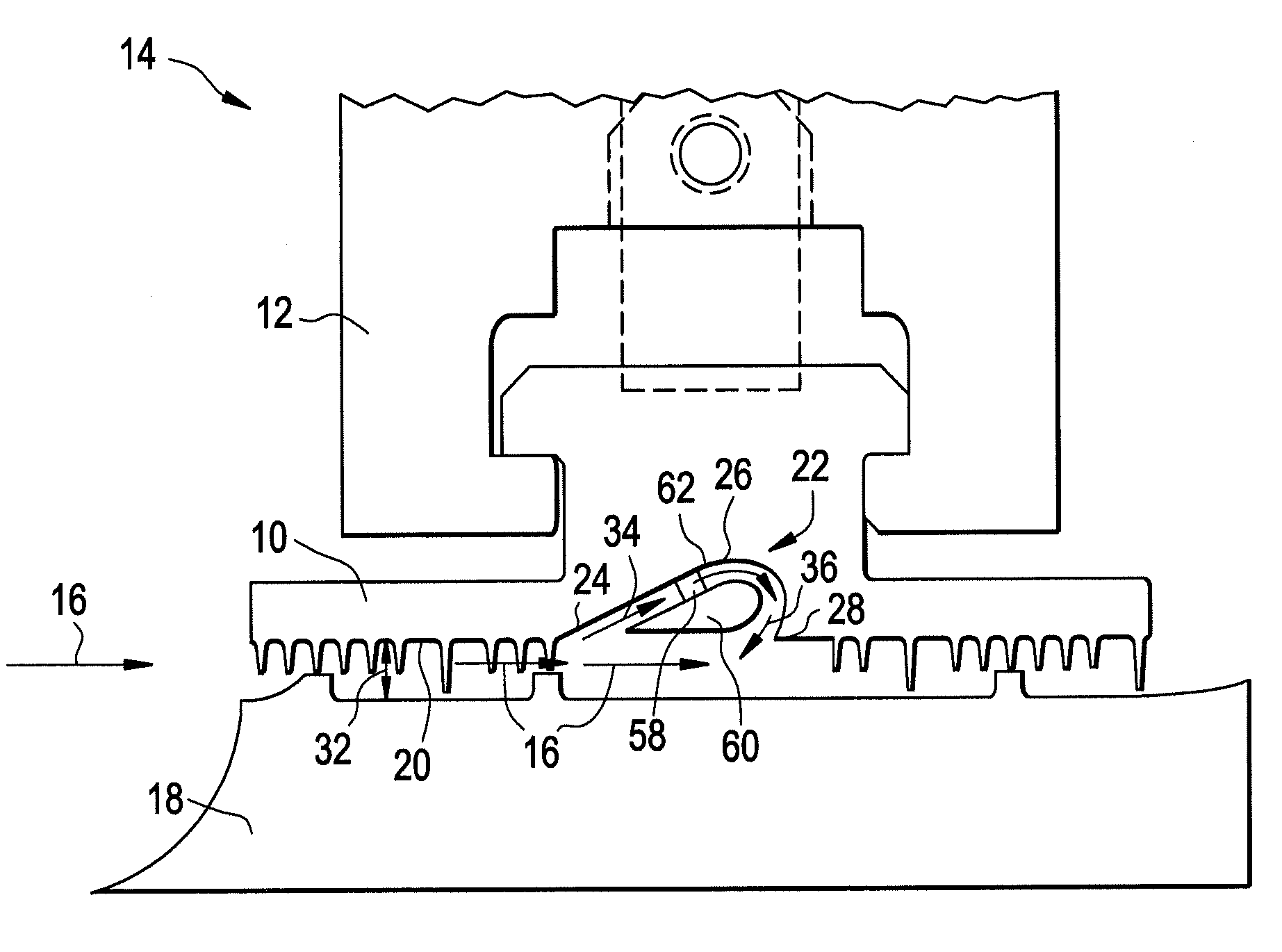
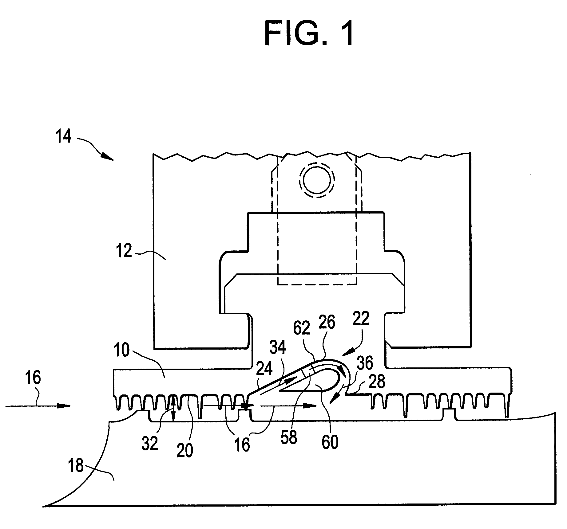
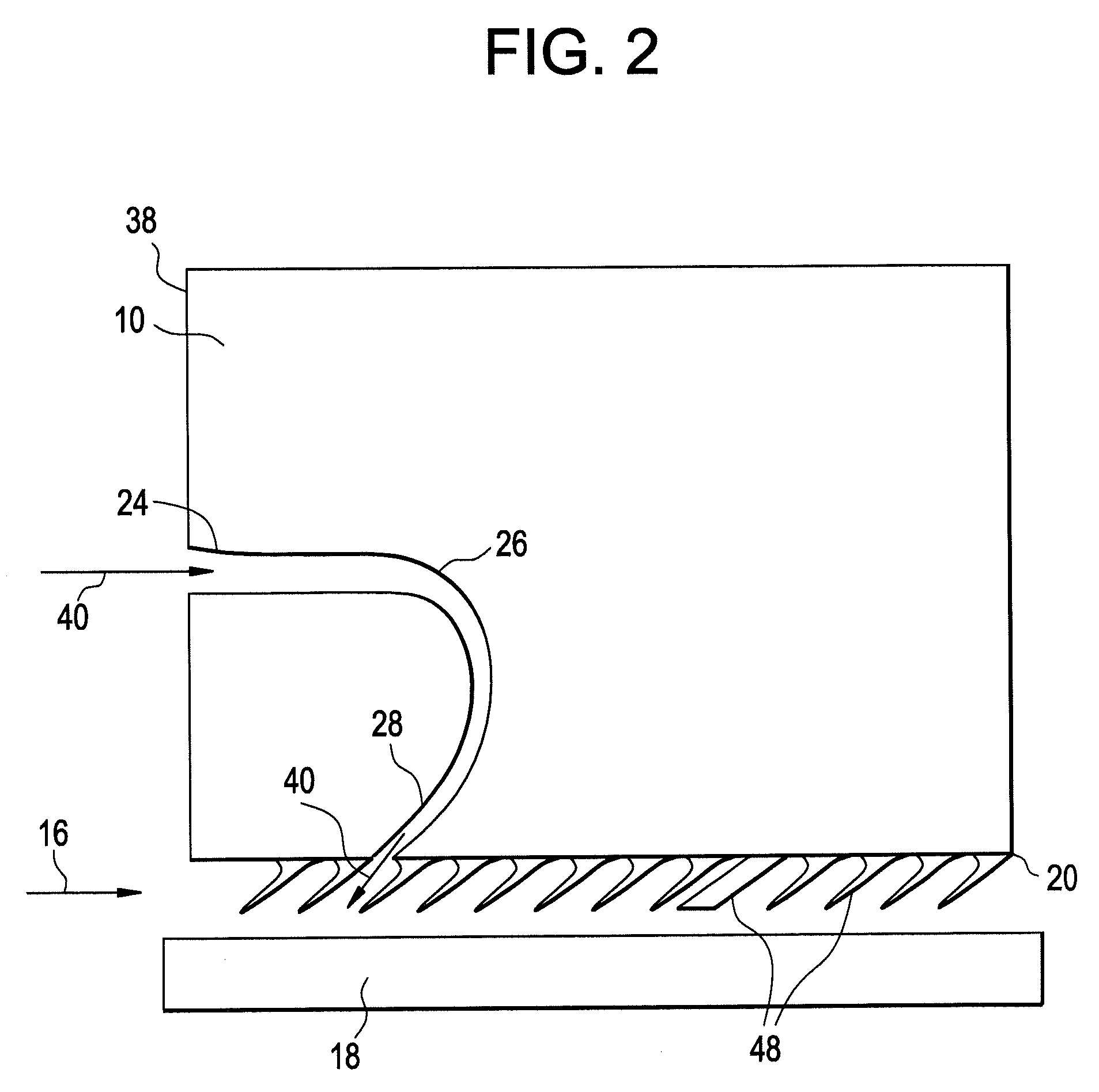
[0016]Shown in FIG. 1 is an embodiment of a packing ring 10 disposed in a casing 12 of a turbomachine 14 with fluid flow through the turbomachine 14 occurring in a generally axial direction 16. The packing ring 10 extends circumferentially around a rotor 18. The packing ring 10 includes a seal face 20 facing the rotor 18. The packing ring 10 includes at least one fluidic diode 22, which includes at least one inlet 24 in flow communication with at least one return channel 26, and at least one outlet 28 in flow communication with the at least one return channel 26. While the embodiment of the packing ring 10 in FIG. 1 has one inlet 24, one return channel 26, and one outlet 28, other configurations having, for example, two inlets 24, two return channels 26, and / or two outlets 28, are contemplated within the scope of the present disclosure. Flow through the turbomachine 14, shown by arrows 16, enters a gap 32 between the seal face 20 and the rotor 18, and a first portion 34 of the flow ...


PUM


Abstract

Disclosed is a seal for turbomachinery including a seal face locatable between a first turbomachinery component and a second turbomachinery component. At least one fluid channel extends through the seal. The at least one fluid channel is capable of injecting fluid flow between the first turbomachinery component and the second turbomachinery component at the seal face thereby disrupting a leakage flow between the first turbomachinery component and the second turbomachinery component. Further disclosed is a turbomachine utilizing the seal.

Description

BACKGROUND[0001]The subject invention relates to turbomachinery. More particularly the subject invention relates to sealing between turbomachinery components.[0002]In a typical turbomachine, seals are utilized at various locations to prevent fluid flow from leaking around a desired flowpath. For example, seals are provided between rotating bucket tips and a stationary casing to direct flow past the buckets rather than between the bucket tips and the casing. Seals may also be utilized between a rotor and a stationary component in the form of one or more packing rings. Typical seal configurations include labyrinth seals, brush seals, abradable seals, patterned abradable seals and compliant plate seals. A labyrinth seal, for example, in the turbomachine typically includes one or more teeth extending from a first component toward a second component to create a tortuous path for fluid flow between the components. During operation of the turbomachinery, however, the teeth may rub on the s...

Claims


Application Information

Patent Timeline
Patent Type & Authority Patents(United States)
IPC IPC(8): F04D27/02
CPCF01D11/04F16J15/442F16J15/443
Inventor TURNQUIST, NORMAN ARNOLDBRUCE, KEVIN L.CERRETELLI, CIROTOURIGNY, JOHN ERNEST
Owner GENERAL ELECTRIC CO
Why Eureka
Try Eureka