Check patentability & draft patents in minutes with Patsnap Eureka AI!

Current source applicable to a controllable delay line and design method thereof

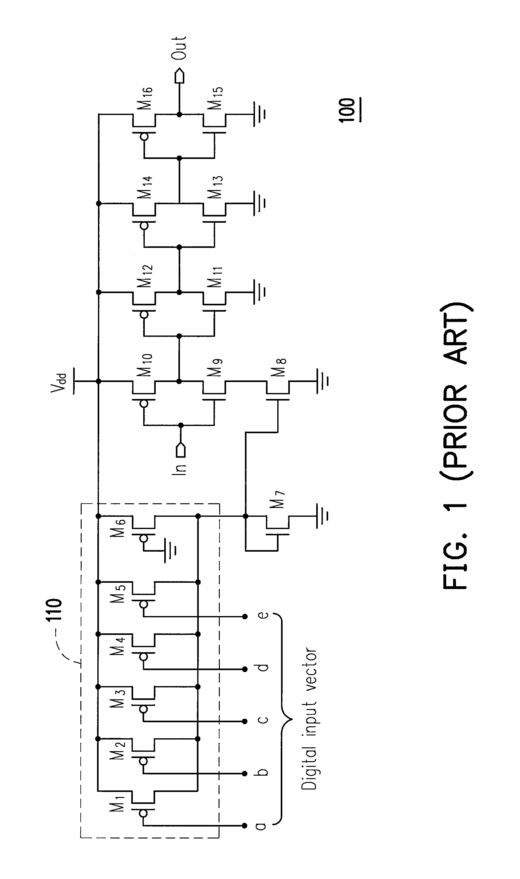
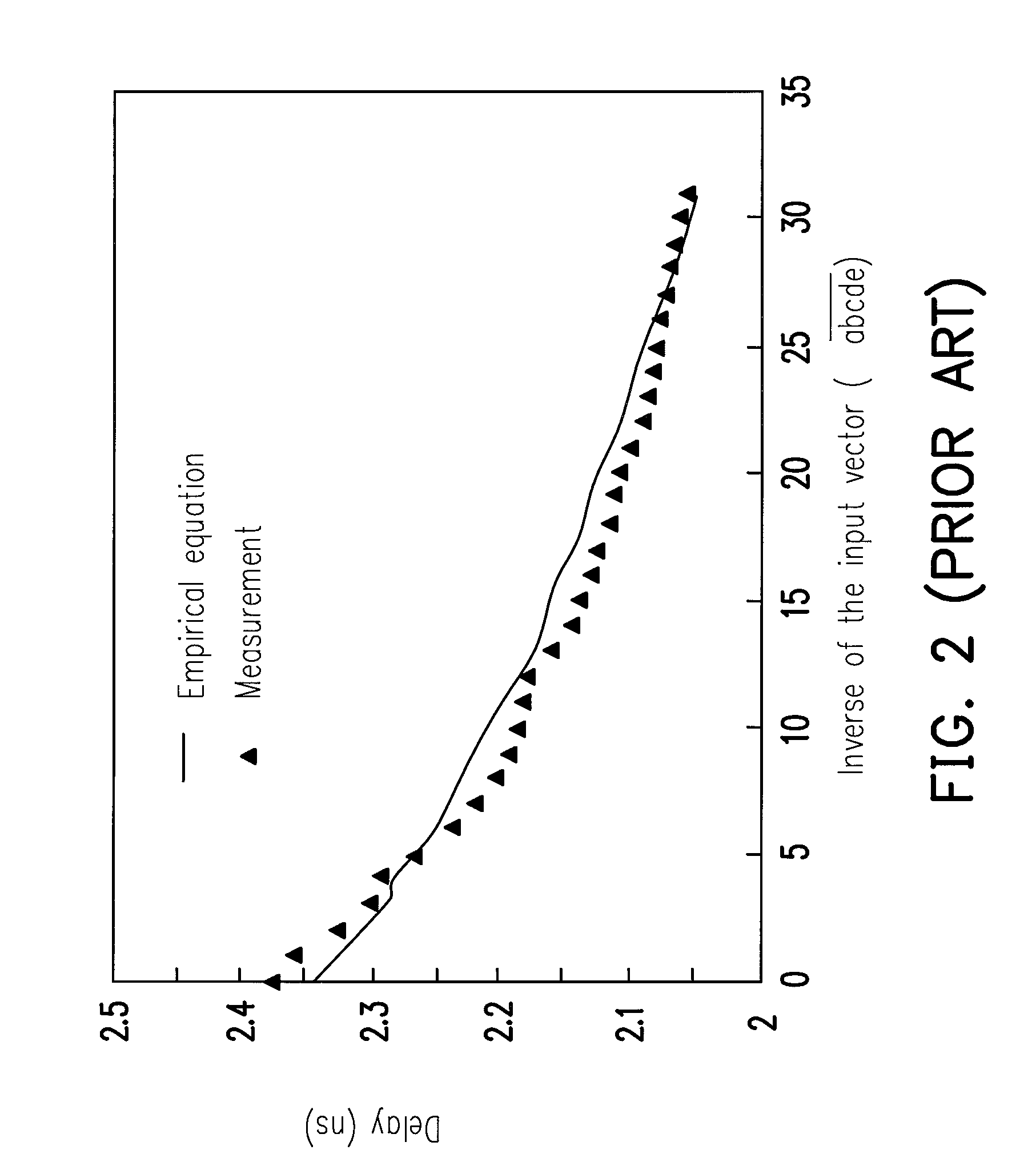
a current source and controllable delay technology, applied in the direction of logic circuit coupling/interface arrangement, pulse technique, instruments, etc., can solve the problem of non-linear delay of the controllable delay line b>100/b>, either derived from empirical equations or obtained from measurement, and the resolution of the controllable delay line is not linear, so as to achieve the effect of small area

Inactive Publication Date: 2011-11-08
FARADAY TECH CORP
View PDF11 Cites 2 Cited by
  • Summary
  • Abstract
  • Description
  • Claims
  • Application Information

AI Technical Summary

Benefits of technology

The design provides linear delay while occupying a smaller area compared to conventional thermometer code current sources, with the ability to determine branch current source sizes for precise delay line performance.

Problems solved by technology

However, due to its binary code control mechanism, the delay of the controllable delay line 100, either derived from empirical equation or obtained from measurement, is non-linear.
This non-linearity has an adverse effect on the resolution of the controllable delay line 100.
However, such a digital delay line imposes very large area overhead due to the amount of inverters and multiplexers required.

Method used


Image

  • Current source applicable to a controllable delay line and design method thereof
  • Current source applicable to a controllable delay line and design method thereof
  • Current source applicable to a controllable delay line and design method thereof

Examples


Embodiment Construction

[0031]Reference will now be made in detail to the present embodiments of the invention, examples of which are illustrated in the accompanying drawings. Wherever possible, the same reference numbers are used in the drawings and the description to refer to the same or like parts.

[0032]FIG. 6 is a schematic diagram showing a current-starved controllable delay line 600 including a current source 610 according to an embodiment of the present invention. FIG. 7 and FIG. 8 are schematic diagrams showing two alternative designs of the current source 610. The designs in FIG. 7 and FIG. 8 are called type I and type II, respectively. As early examples, the current sources in FIG. 7 and FIG. 8 are 3-bit current sources whose output currents are controlled by the 3-bit input code D0-D2. D2 is the MSB and D0 is the LSB. As discussed below, the designs in FIG. 7 and FIG. 8 may be easily modified to N-bit current sources, wherein N is an arbitrary positive integer.

[0033]FIG. 7 shows the current sour...


PUM


Abstract

A current source and a method for designing the current source are provided. The current source is designed by a recursive rule and enables controllable delay lines to provide linear delay and occupy smaller area than conventional controllable delay lines with thermometer code current sources do.

Description

BACKGROUND OF THE INVENTION[0001]1. Field of the Invention[0002]The present invention relates to a current source applicable to a controllable delay line and a method for designing the current source.[0003]2. Description of the Related Art[0004]FIG. 1 is a schematic diagram showing a conventional controllable delay line 100. six p-channel metal oxide semiconductor field effect transistors (PMOSFETs) M1-M6 constitute six current branches of the current source 110 of the controllable delay line 100. The input signals a, b, c, d, and e constitute the digital input vector of the current source 110. The digital input vector controls the on / off condition of the PMOSFETs M1-M5, which controls the total output current of the current source 110. The output current of the current source 110 determines the delay of the controllable delay line 100.[0005]The controllable delay line 100 has a small area due to its analog design. As shown in FIG. 2, the delay of the controllable delay line 100 is ...

Claims


Application Information

Patent Timeline
Patent Type & Authority Patents(United States)
IPC IPC(8): H03K19/0175
CPCH03M1/82H03K5/133H03K2005/00065
Inventor CHEN, CHI-CHEHO, JUNG-CHI
Owner FARADAY TECH CORP
Features
  • R&D
  • Intellectual Property
  • Life Sciences
  • Materials
  • Tech Scout
  • Unparalleled Data Quality
  • Higher Quality Content
  • 60% Fewer Hallucinations
Learn More