Optical recording medium, and optical information device

a technology of optical information and optical recording medium, which is applied in the direction of mechanical recording, disposition/mounting of heads, instruments, etc., can solve the problems of information recording/reproducing, affecting deteriorating so as to improve the quality of servo signals and reproduction signals

Active Publication Date: 2011-11-08
PANASONIC CORP
View PDF20 Cites 0 Cited by
  • Summary
  • Abstract
  • Description
  • Claims
  • Application Information

AI Technical Summary

Benefits of technology

[0020]In view of the above, an object of the invention is to provide an optical recording medium and an optical information device that enable to improve the quality of a servo signal and a reproduction signal.
[0023]According to the invention, the thicknesses t1, t2, t3, and t4 obtained by converting the shape-wise thicknesses tr1, tr2, tr3, and tr4 of the cover layer, the first intermediate layer, the second intermediate layer, and the third intermediate layer satisfy it |t1−(t2+t3+t4)|≧1 μm, a difference between any two values of the thicknesses t1, t2, t3, and t4 is set to 1 μm or more in any case, and |(t1+t2)−(t3+t4)|≧1 μm. This enables to prevent light from forming an image on the backside of the surface of the optical recording medium, and suppress coherence between reflected light from the information recording surfaces to thereby improve the quality of a servo signal and a reproduction signal. Further, since the distance between the surface of the optical recording medium and the information recording surface closest to the surface of the optical recording medium can be set to a large value, deterioration of a reproduction signal in the case where there is a damage or a smear on the surface of the optical recording medium can be suppressed.

Problems solved by technology

As described above, there is a problem that reflected light from the fourth information recording surface 401d to be read is superimposed and mixed with reflected light which forms an image on the backside of the other surface, with the result that information recording / reproducing is obstructed.
Since the brightness / darkness distribution is varied depending on a change in phase difference with respect to reflected light from the other surface, resulting from a small thickness variation of an intermediate layer in an in-plane direction of an optical disc, the quality of a servo signal and a reproduction signal may be considerably deteriorated.
As a result, coherence between a light flux reflected on the backside of the surface 401z, and a light flux reflected on a targeted information recording surface to be recorded or reproduced is generated in the similar manner as in the case of a light flux reflected on the backside of the other information recording surfaces, which may considerably deteriorate the quality of a servo signal and a reproduction signal.
Thus, both of the publications do not consider an influence of a refractive index of a transparent material to the quality of a servo signal and a reproduction signal.

Method used


Image

  • Optical recording medium, and optical information device
  • Optical recording medium, and optical information device
  • Optical recording medium, and optical information device

Examples


Embodiment Construction

[0038]In the following, an embodiment of the invention is described referring to the accompanying drawings. The following embodiment is merely an example embodying the invention, and does not limit the technical scope of the invention.

[0039]Firstly, an optical recording medium embodying the invention is described referring to FIGS. 1 and 2.

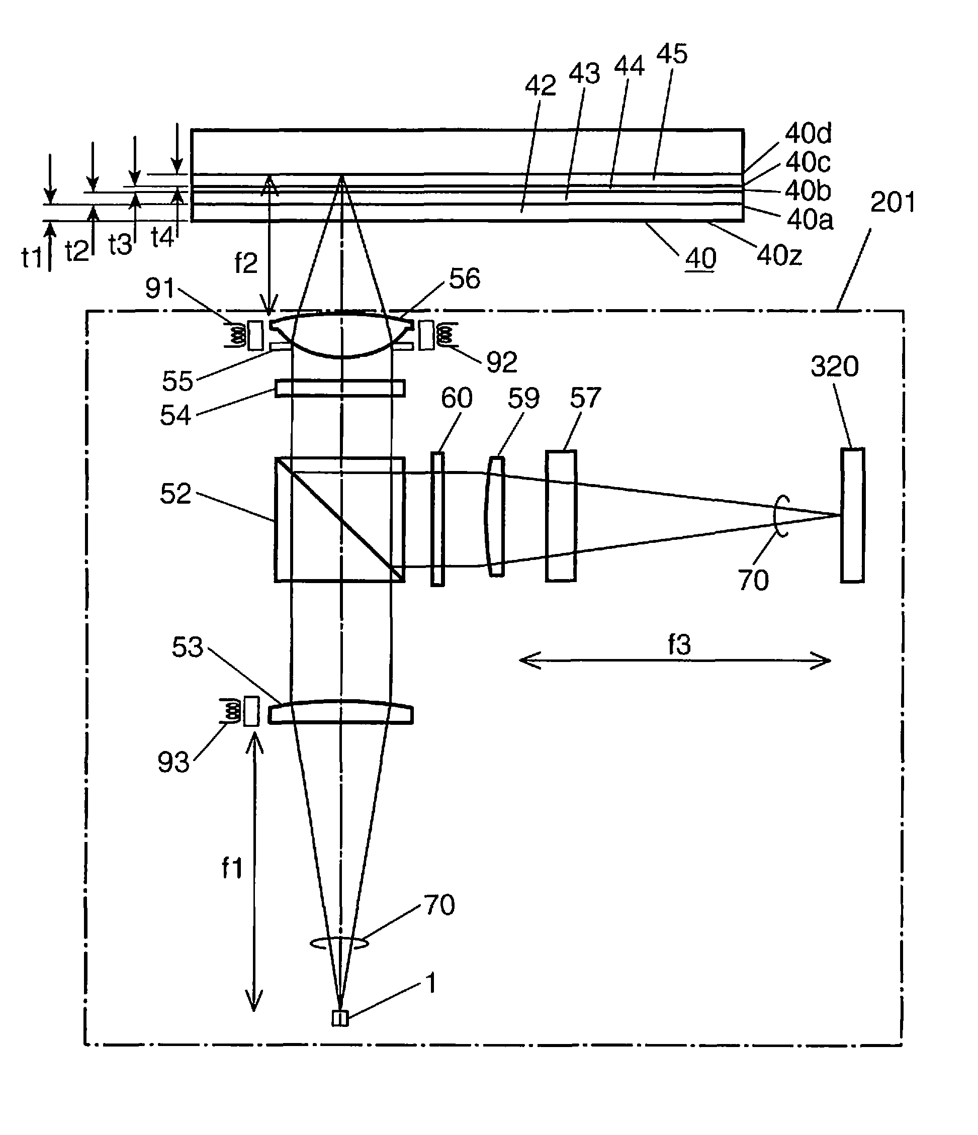
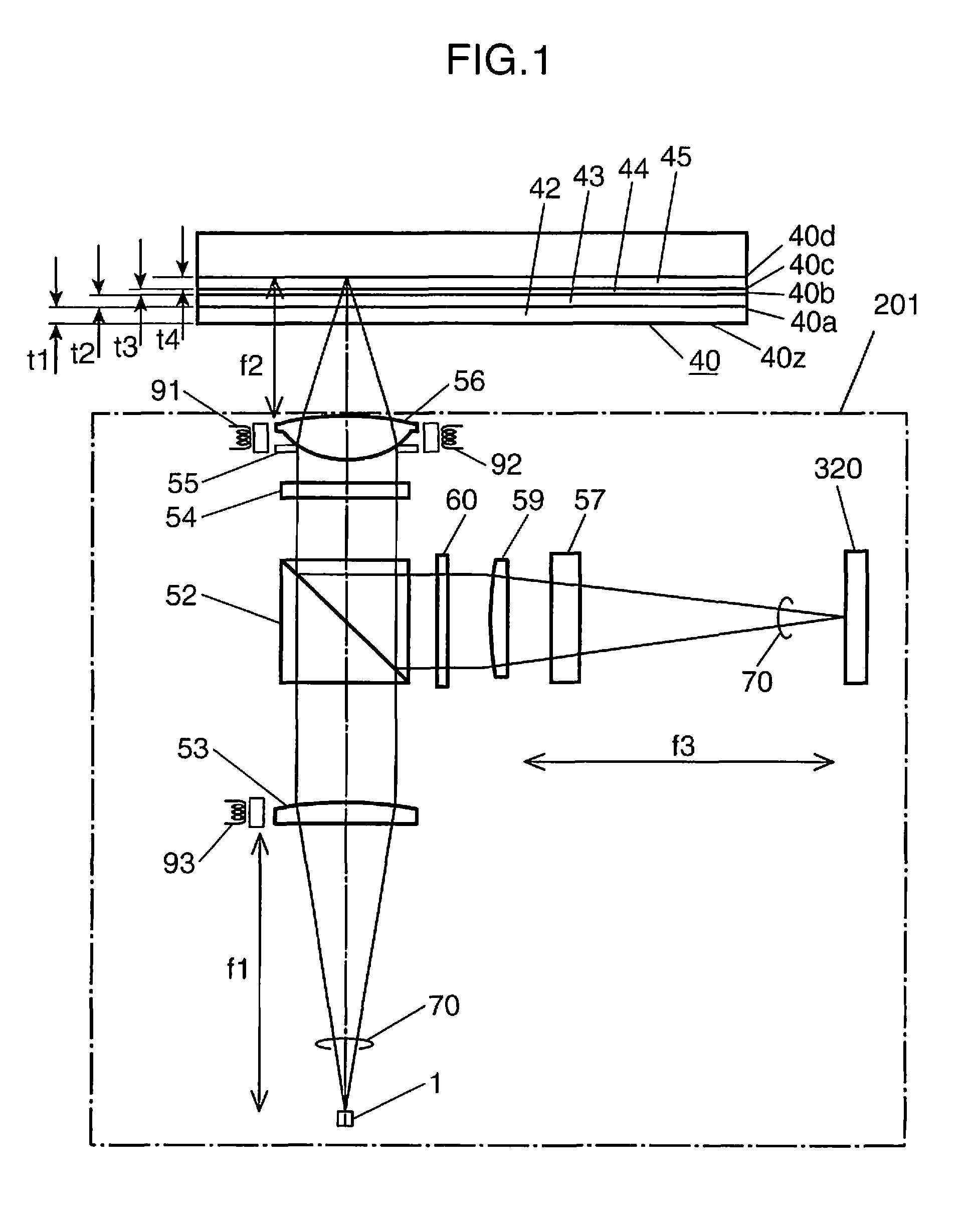
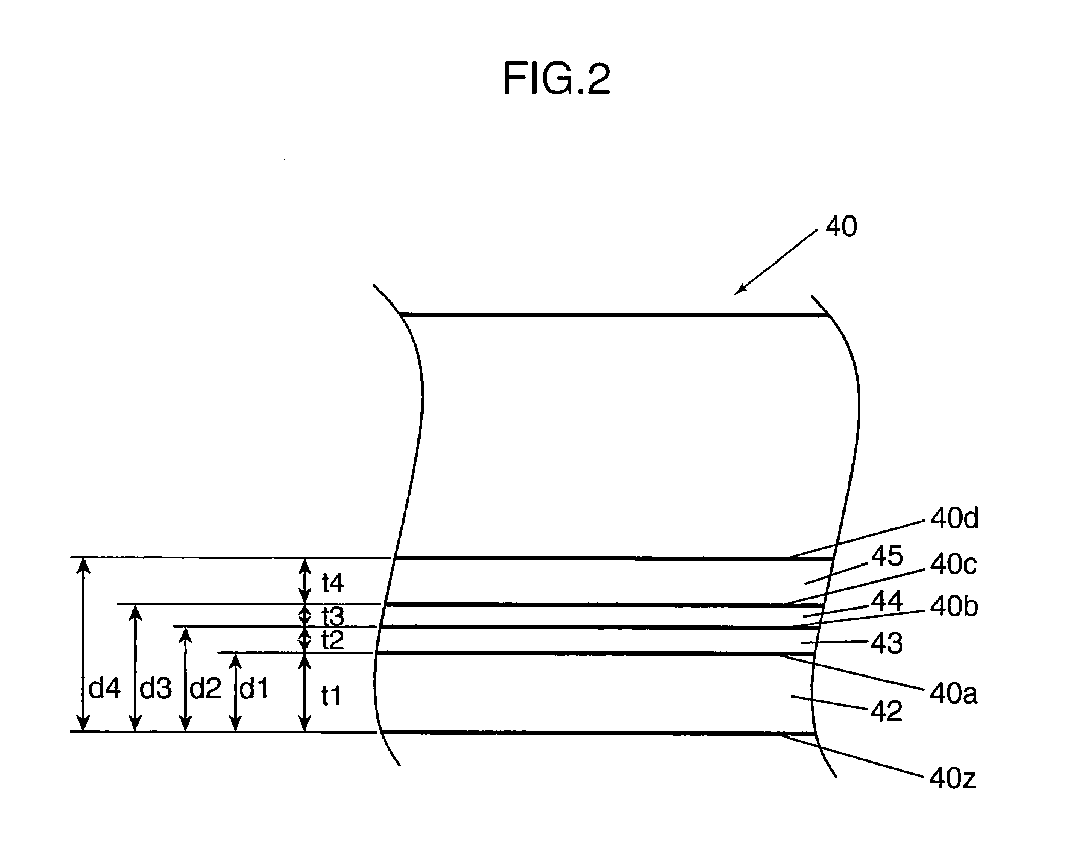
[0040]FIG. 1 is a diagram showing a schematic arrangement of an optical recording medium embodying the invention, and an optical head device. FIG. 2 is a diagram showing a layer structure of the optical recording medium in the embodiment. An optical head device 201 irradiates blue laser light whose wavelength λ is 405 nm onto an optical recording medium 40 to reproduce a signal recorded in the optical recording medium 40. Since the arrangement and the operation of the optical head device 201 shown in FIG. 1 are substantially the same as the arrangement and the operation of the optical head device shown in FIG. 13, detailed description thereof is o...


PUM

PropertyMeasurementUnit
refractive indexaaaaaaaaaa
thicknesses t1aaaaaaaaaa

Abstract

An optical recording medium and an optical information device that improve the quality of a servo signal and a reproduction signal. In the optical recording medium, when shape-wise thicknesses tr1, tr2, tr3, and tr4 of a cover layer (42), a first intermediate layer (43), a second intermediate layer (44), and a third intermediate layer (45) are respectively converted into thicknesses t1, t2, t3, and t4 of the respective corresponding layers each having a predetermined refractive index “no”, a defocus amount with respect to a layer having a refractive index nrα and a thickness trα (satisfying: 1≦α≦n (where α is a positive integer and n is an integer of 4 or more)), and a defocus amount with respect to a layer having the refractive index “no” and a thickness tα (satisfying: 1≦α≦n (where α is a positive integer and n is an integer of 4 or more)) are equal to each other. Further, the thicknesses t1, t2, t3, and t4 satisfy |t1−(t2+t3+t4)|≧1 μm, a difference between any two values of the thicknesses t1, t2, t3, and t4 is set to 1 μm or more, and |(t1+t2)−(t3+t4)|≧1 μm.

Description

[0001]This application claims the benefit of U.S. Non-Provisional application Ser. No. 12 / 269,289, filed Nov. 12, 2008.TECHNICAL FIELD[0002]The present invention relates to an optical recording medium for information recording or reproducing by irradiated light, and an optical information device for recording or reproducing information with respect to the optical recording medium, and more particularly to an interlayer structure of an optical recording medium having three or more information recording surfaces.BACKGROUND ART[0003]There are known optical discs called as DVD or BD (Blu-ray disc), as examples of the commercially available high-density and large-capacity optical information recording media. In recent years, the optical discs have become widely used as recording media for recording images, music, and computer-readable data. There also has been proposed an optical disc having plural recording layers, as disclosed in Patent literature 1 and Patent literature 2, to further ...

Claims


Application Information

Patent Timeline
Patent Type & Authority Patents(United States)
IPC IPC(8): G11B7/00G11B7/135
CPCG11B7/24038G11B7/005G11B7/09G11B7/13925G11B2007/0013
Inventor KOMMA, YOSHIAKIANZAI, JOJITSUKUDA, MASAHIKOHINO, YASUMORI
Owner PANASONIC CORP
Why Eureka
Try Eureka