Method and apparatus for determining the attachment position of a motion sensing apparatus

a motion sensing apparatus and attachment position technology, applied in the direction of instruments, apparatus for force/torque/work measurement, distance measurement, etc., can solve problems such as incorrect function

Active Publication Date: 2011-11-08
GARMIN
View PDF53 Cites 174 Cited by
  • Summary
  • Abstract
  • Description
  • Claims
  • Application Information

AI Technical Summary

Benefits of technology

[0126]It is believed that embodiments of the present invention and many of its attendant advantages will be understood by the foregoing description, and it will be apparent that various changes may be made in the form, construction and arrangement of the components thereof without departing from the scope and spirit of the invention or without sacrificing all of its material advantages. The form herein before described being merely an explanatory embodiment thereof, it is the intention of the following claims to encompass and include such changes.

Problems solved by technology

Thus, if a motion sensing apparatus is attached to an incorrect location, it may function incorrectly.

Method used


Image

  • Method and apparatus for determining the attachment position of a motion sensing apparatus
  • Method and apparatus for determining the attachment position of a motion sensing apparatus
  • Method and apparatus for determining the attachment position of a motion sensing apparatus

Examples


Embodiment Construction

[0028]The following detailed description of various embodiments of the invention references the accompanying drawings which illustrate specific embodiments in which the invention can be practiced. The embodiments are intended to describe aspects of the invention in sufficient detail to enable those skilled in the art to practice the invention. Other embodiments can be utilized and changes can be made without departing from the scope of the present invention. The following detailed description is, therefore, not to be taken in a limiting sense. The scope of the present invention is defined only by the appended claims, along with the full scope of equivalents to which such claims are entitled.

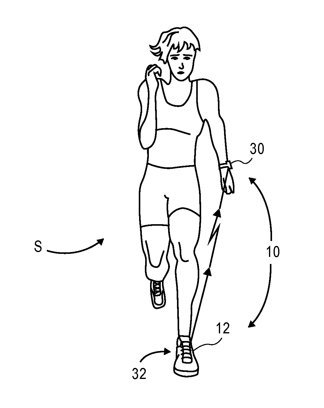
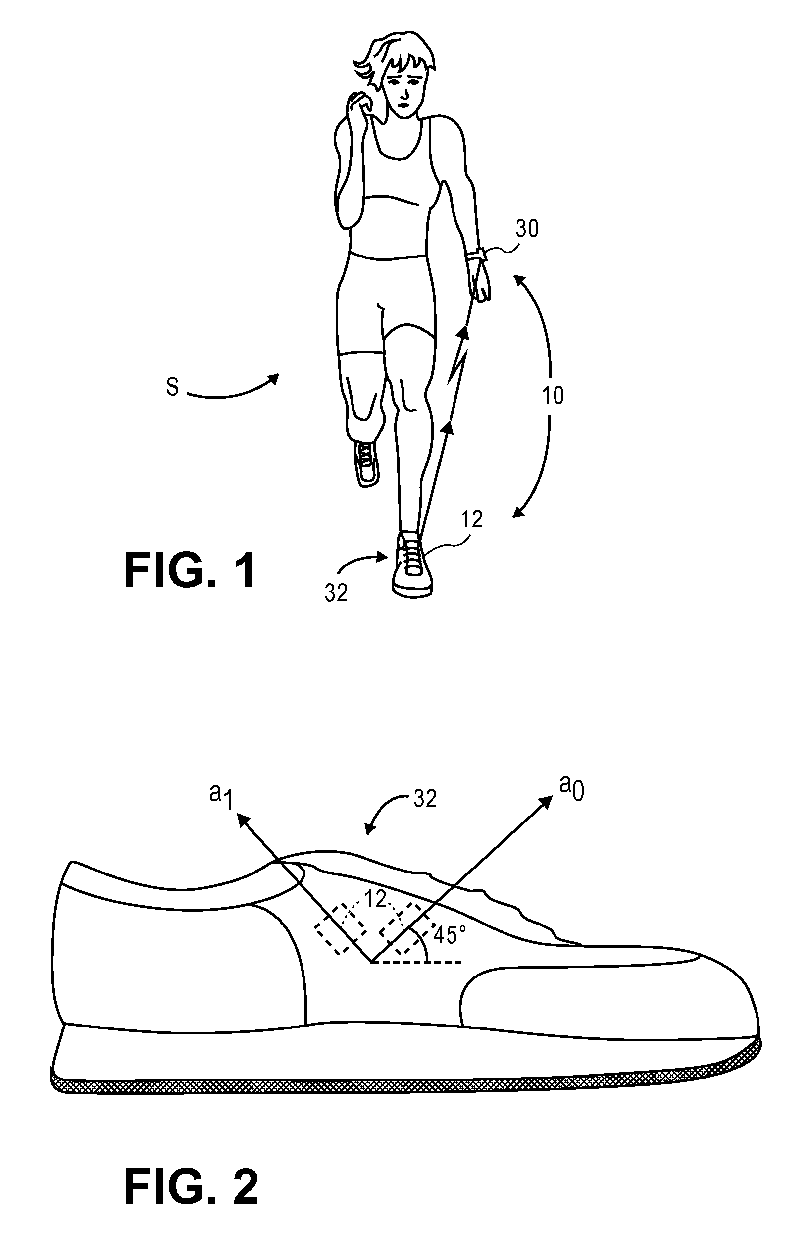
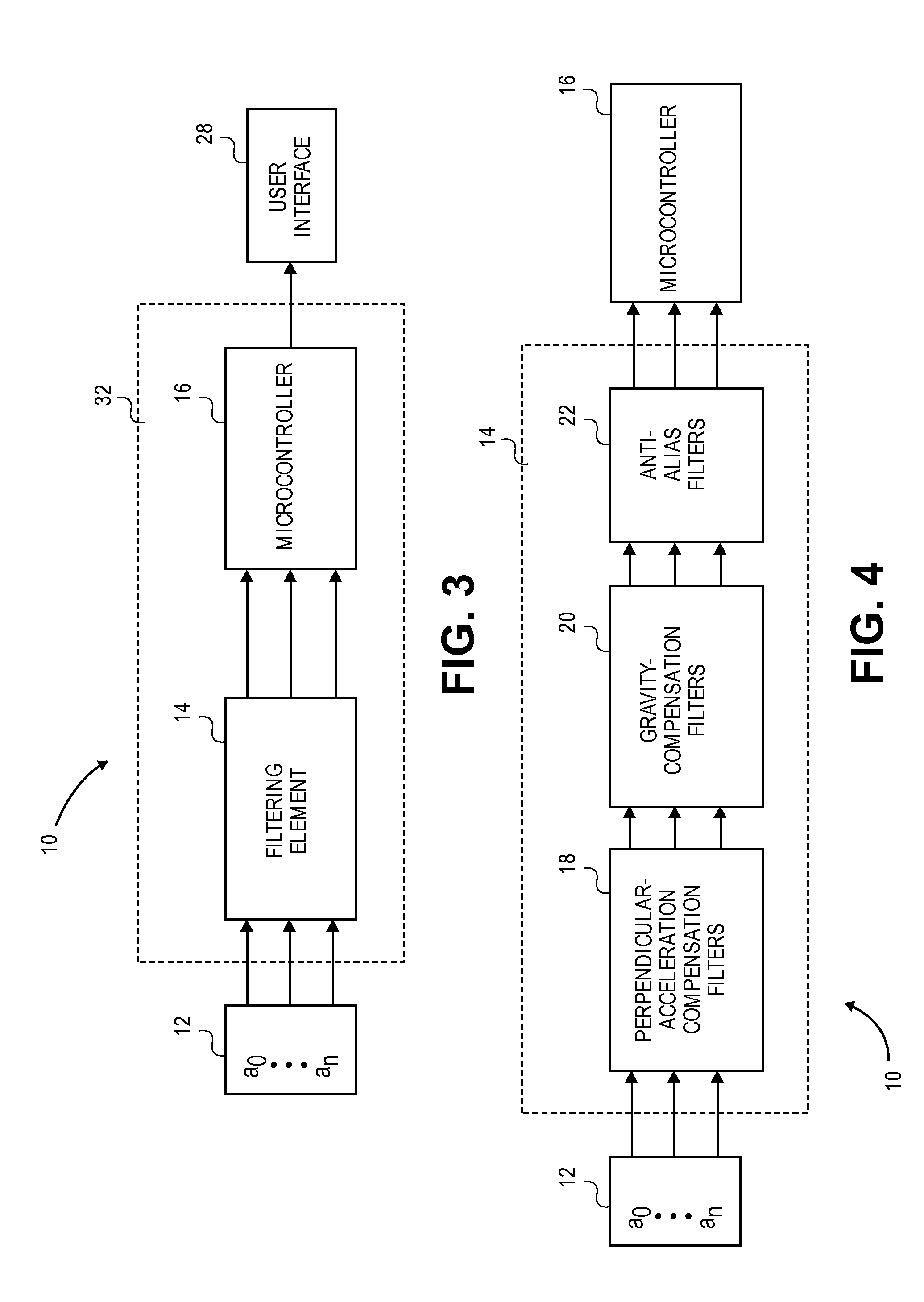
[0029]Various embodiments of the present invention provide a motion sensing apparatus 10 operable to determine its attachment position based on one or more acceleration measurements. The apparatus 10 may select a motion analysis algorithm based on the identified attachment position and determine ...


PUM


Abstract

A motion sensing apparatus generally comprising a housing unit operable to be attached to an object at an attachment position, an accelerometer operable to provide a signal corresponding to an acceleration measurement; and a processing system. The processing system is operable to acquire the signal corresponding to the acceleration measurement and analyze the acquired acceleration measurement to identify the attachment position of the housing unit.

Description

RELATED APPLICATIONS[0001]The present application claims the benefit of U.S. Provisional Application No. 60 / 889,227, entitled “MOTION CLASSIFICATION SYSTEM AND METHOD,” filed Feb. 9, 2007, and is also a continuation-in-part of U.S. patent application Ser. No. 11 / 681,032, entitled “METHOD AND APPARATUS FOR ESTIMATING A MOTION PARAMETER,” filed Mar. 1, 2007, which in turn claims the benefit of U.S. Provisional Application No. 60 / 778,793, entitled “METHOD AND SYSTEM FOR QUICK DISTANCE MEASUREMENT,” filed Mar. 3, 2006. Each of the above-identified applications is incorporated herein by reference.BACKGROUND[0002]1. Field[0003]Embodiments of the present invention relate to methods and apparatuses for determining the attachment position of a motion sensing apparatus. More particularly, various embodiments of the invention provide methods and apparatuses operable to determine the attachment position of a motion sensing apparatus using acceleration measurements sensed by the motion sensing a...

Claims


Application Information

Patent Timeline
Patent Type & Authority Patents(United States)
IPC IPC(8): G01P15/02
CPCA63B24/0062G06K9/00536G01C22/006A63B69/0028A63B2071/068A63B2220/12A63B2220/20A63B2220/22A63B2220/30A63B2220/64A63B2220/70A63B2220/72A63B2220/74A63B2220/836A63B2225/20A63B2225/50A63B2230/06A63B2230/75G06F2218/12
Inventor KULACH, CHRISTOPHER J.ROONEY, JAMES K.MACDONALD, PAUL R.STIRLING, ROSS G.
Owner GARMIN
Why Eureka
Try Eureka