

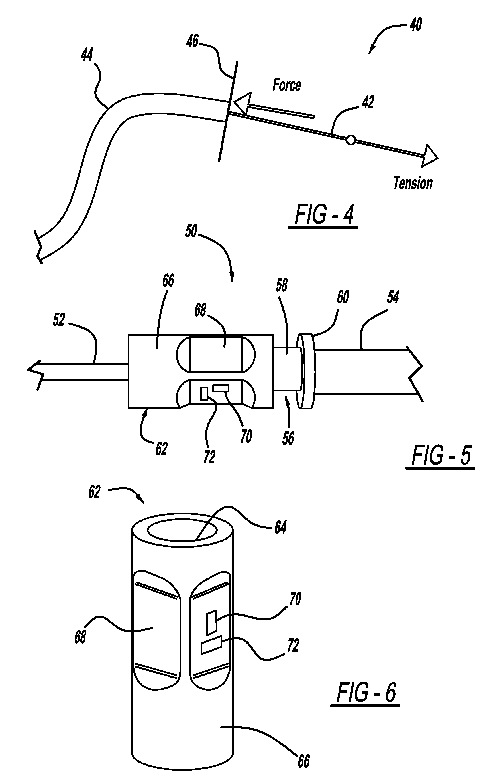
Sensing the tendon tension through the conduit reaction forces
a technology of reaction force and tendon, applied in the direction of force/torque/work measurement apparatus, instruments, person identification, etc., can solve the problems of insufficient sensing of tendon tension, inability to accurately measure the strain of the strain gauge sensor, and difficulty in direct sensing tendon tension
- Summary
- Abstract
- Description
- Claims
- Application Information
AI Technical Summary
Benefits of technology
Problems solved by technology
Method used
Image

Examples
Embodiment Construction
[0020]The following discussion of the embodiments of the invention directed to a tendon tension sensor for a robotic arm that measures a reactive force on a conduit through which the tendon is threaded is merely exemplary in nature, and is in no way intended to limit the invention or its applications or uses. For example, the present invention has application to measure the tension on a tendon in a robotic arm. However, as will be appreciated by those skilled in the art, the tendon tension sensor will have other application.
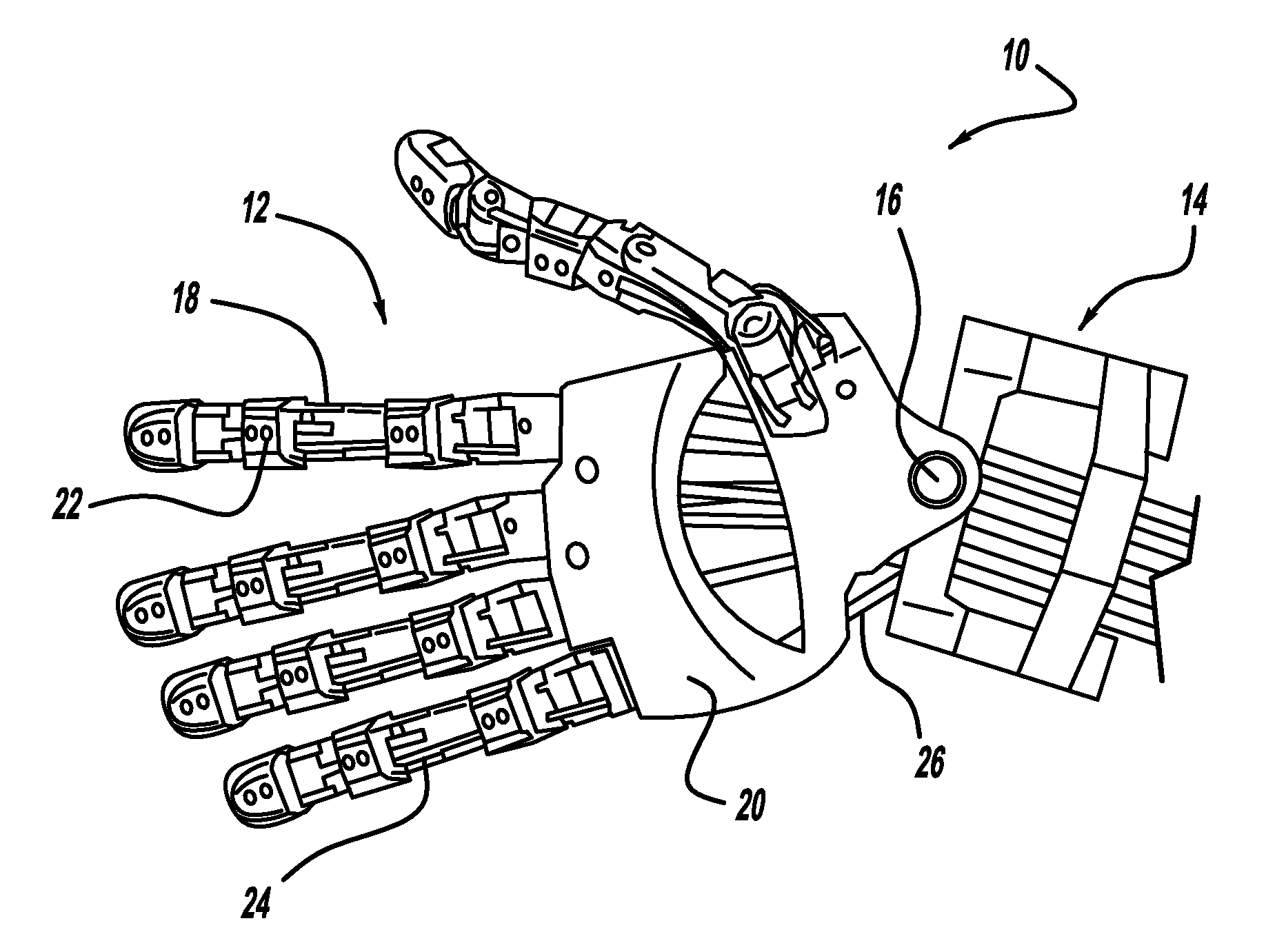
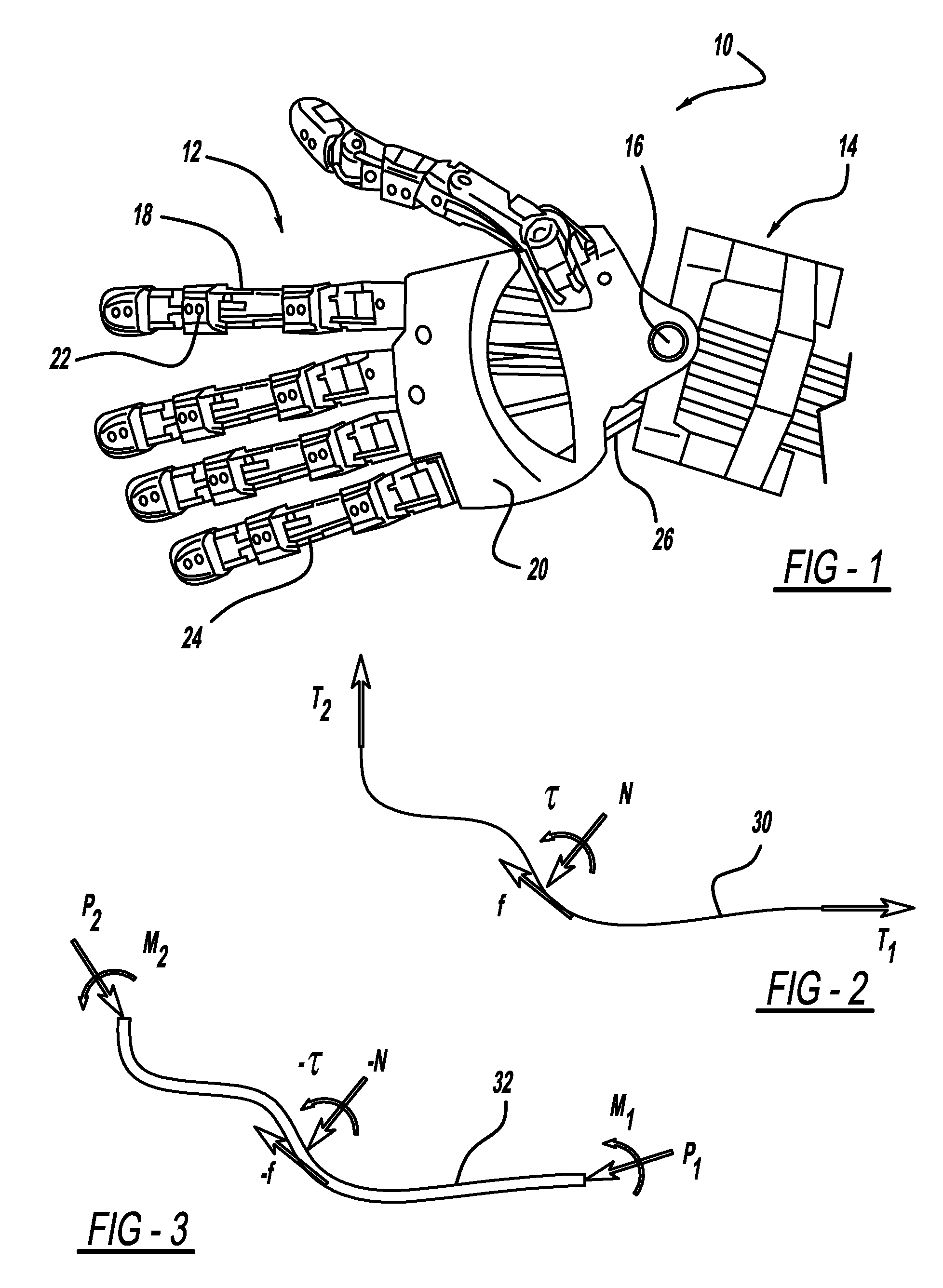
[0021]FIG. 1 is a perspective view of part of a robotic arm 10 including a robotic hand 12 and a robotic wrist 14 pivotable relative to each other by a pivot joint 16. The robotic hand 12 includes robotic fingers 18 and a robotic palm 20. The robotic fingers 18 include a plurality of joints 22 that are actuatable to allow the robotic hand 12 to grasp certain components, as is well understood in the art. Tendons 24 are coupled to the joints 22 and are actuatable b...
PUM
| Property | Measurement | Unit |
|---|---|---|
| tension | aaaaa | aaaaa |
| area | aaaaa | aaaaa |
| reaction forces | aaaaa | aaaaa |
Abstract
Description
Claims
Application Information