Roller holder for motion guide device

a technology of motion guide device and roller holder, which is applied in the direction of bearings, shafts and bearings, bearings, etc., can solve the problems of affecting the movement of the roller holder. , to achieve the effect of facilitating sliding movement and preventing the impact on the roller holder

Active Publication Date: 2011-11-15
HIWIN TECH
View PDF8 Cites 6 Cited by
  • Summary
  • Abstract
  • Description
  • Claims
  • Application Information

AI Technical Summary

Benefits of technology

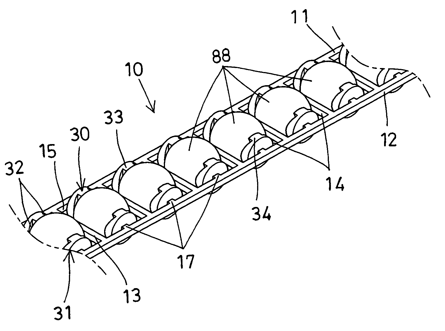
[0015]The primary objective of the present invention is to provide a roller holder including a number of rollers alternately disposed and arranged in different directions for engaging between two moving members and for preventing the impact onto the roller holder and for facilitating the sliding movement between the two moving members.
[0016]In accordance with one aspect of the invention, there is provided a roller holder for engaging between two moving members, the roller holder comprising two longitudinal rods disposed parallel to each other, a number of couplers disposed between the rods for coupling the rods together and for forming a number of compartments between the rods and the couplers, a number of rolling members received in the compartments of the roller holder respectively, and two retaining devices disposed in each of the compartments of the roller holder and attached to the rods and facing toward each other for engaging with the rolling members and for retaining the rolling members in the compartments and between the rods and the couplers of the roller holder, and for preventing the retaining devices from being disposed between the rolling members and for preventing the retaining devices from being impacted by the rolling members.
[0022]The first and the second retainers each preferably include a curved inner peripheral surface for smoothly engaging with the rolling members with a point-contact, a line-contact or a surface-contact.

Problems solved by technology

However, the interposing portions are connected and disposed between the ball bearing members or rolling bodies, and the ball bearing members or rolling bodies will impact onto and will scrape or scrub the interposing portions particularly when the endless retainer moves in a fast speed between the two moving members such that the abrasion or scraping between the interposing portions and the ball bearing members or rolling bodies will be greatly increased and such that the interposing portions will be quickly worn out.
However, similarly, the holding parts are also connected and disposed between the rolling elements which will impact onto the holding parts when the rolling element string moves in a fast speed between the two moving members such that the abrasion or scraping between the holding parts and the rolling elements will be greatly increased and such that the holding parts will be quickly worn out or damaged.
However, similarly, the retainers are also connected and disposed between the rolling elements which will impact onto the retainers when the rolling element chain arrangement moves in a fast speed between the two moving members such that the abrasion or scraping between the retainers and the rolling elements will be greatly increased and such that the retainers will be quickly worn out or damaged.

Method used


Image

  • Roller holder for motion guide device
  • Roller holder for motion guide device
  • Roller holder for motion guide device

Examples


Embodiment Construction

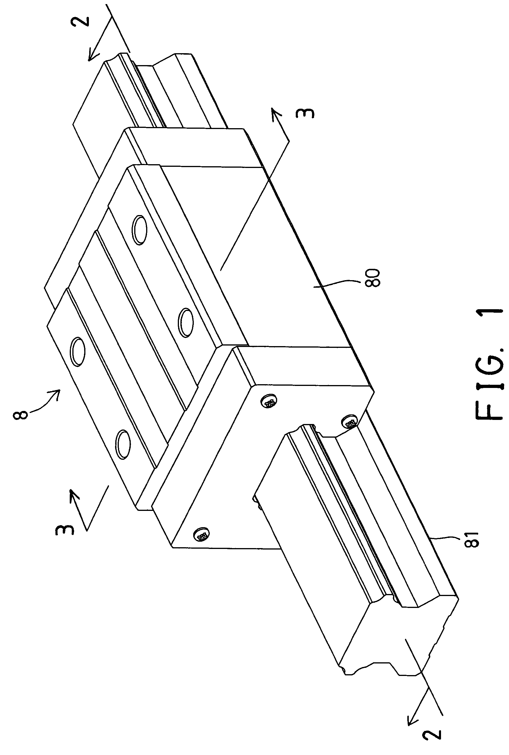
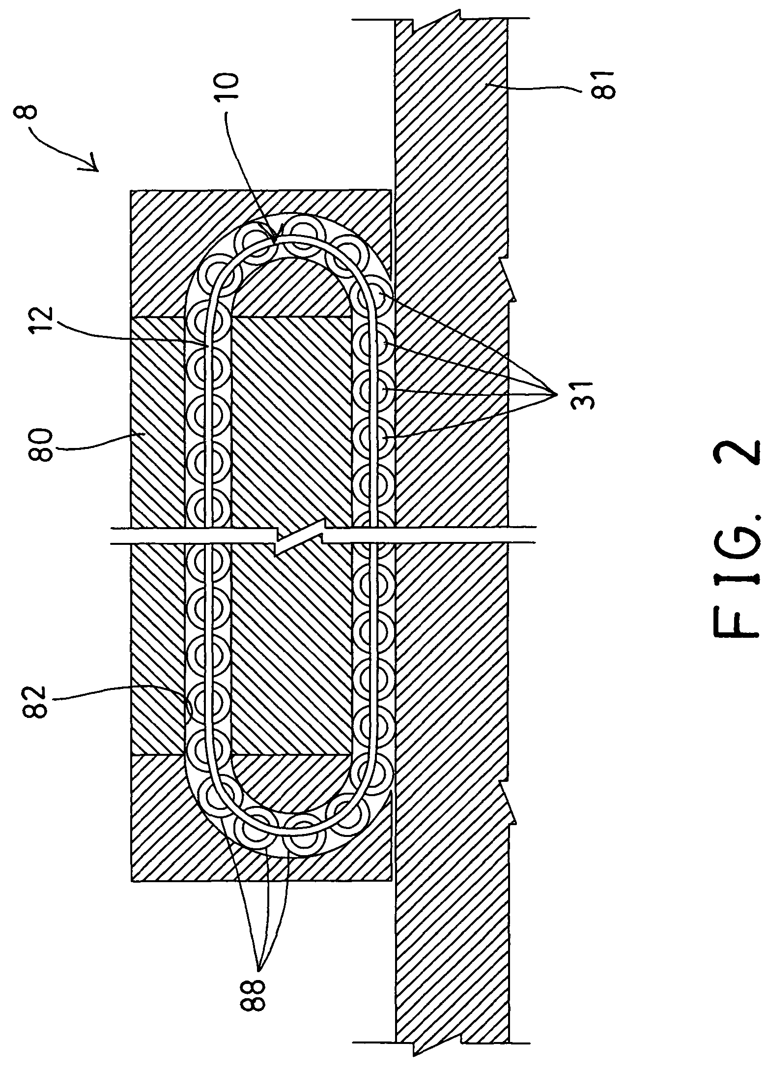
[0035]Referring to the drawings, and initially to FIGS. 1, 2 and 3, a roller holder 10 in accordance with the present invention is provided for being engaged in a linear motion guide device 8, such as engaged between a slider 80 and a track rail 81 or an endless ball guiding passage or channel 82 of the linear motion guide device 8, and particularly engaged between the guiding channels 82 of the slider 80 and the track rail 81 (FIGS. 2-4) for facilitating the sliding movement between the slider 80 and the track rail 81 of the linear motion guide device 8.

[0036]Similarly, the roller holder 10 in accordance with the present invention may also be provided for being engaged in a screw shaft device (not shown), such as engaged between a screw member and a nut member of the screw shaft device, and particularly engaged between the thread members of the screw member and the nut member for facilitating the sliding movement between the two moving members or between the screw member and the nu...


PUM


Abstract

A roller holder includes a number of couplers disposed between two longitudinal rods for coupling the rods together and for forming a number of compartments to receive rolling members, and two retaining devices disposed in each compartment of the roller holder and attached to the rods for retaining the rolling members in the compartments and between the rods and the couplers of the roller holder, and for preventing the retaining devices from being impacted by the rolling members, the retaining devices each include a projected portion located above the rods and a protruded portion located below the rods and the couplers for engaging with the rolling members.

Description

BACKGROUND OF THE INVENTION[0001]1. Field of the Invention[0002]The present invention relates to a roller holder, and more particularly to a roller holder having rollers arranged in different directions for engaging between two moving members and for preventing the impact onto the roller holder and for facilitating the sliding movement between the two moving members.[0003]2. Description of the Prior Art[0004]Typical screw shafts comprise a screw member threaded into a nut member, or relatively, a nut member engaged or threaded onto a screw member, and a number of balls engaged in the threads of the nut member and the screw member for facilitating the rotational and / or sliding movement between the nut member and the screw member.[0005]Typical linear motion guide devices or other motion guide devices also comprise two moving members, such as a track rail and a slider slidably engaged with each other, and a number of balls or rollers or rolling members engaged between the two moving me...

Claims


Application Information

Patent Timeline
Patent Type & Authority Patents(United States)
IPC IPC(8): F16C29/06
CPCF16C29/0647F16C33/3825
Inventor CHEN, TSUNG-JENCHIOU, CHIA-HUEI
Owner HIWIN TECH
Why Eureka
Try Eureka