Single-bearing fan structure

a single-bearing, fan technology, applied in the direction of machines/engines, mechanical equipment, liquid fuel engines, etc., can solve the problems of failure of products or even more serious problems, noise, and endanger products, so as to reduce the noise produced by the fan structure, reduce the cost, and ensure the stability of the fan structure

Active Publication Date: 2011-11-15
ASIA VITAL COMPONENTS(SHEN ZHEN) CO LTD
View PDF4 Cites 4 Cited by
  • Summary
  • Abstract
  • Description
  • Claims
  • Application Information

AI Technical Summary

Benefits of technology

A primary object of the present invention is to provide a single-bearing fan structure, which has a blade hub being axially supported by two elastic elements and radially supported by one single bearing to achieve stable operation of the fan structure.
Another object of the present invention is to provide a single-bearing fan structure that can be manufactured at reduced cost.
A further object of the present invention is to provide a single-bearing fan structure that can reduce noise produced by the fan structure during the operation thereof.
A still further object of the present invention is to provide a single-bearing fan structure that enables extended service life of the fan.
A still further object of the present invention is to provide a single-bearing fan structure that can be applied to fans of different thicknesses.
To achieve the above and other objects, the single-bearing fan structure according to the present invention includes a fan frame, a blade hub, a retainer, a first elastic element, and a second elastic element. The fan frame includes a bearing cup having a bearing received therein. The bearing cup has a first end and a second end, the first end has a lip portion radially protruded toward a centerline of the bearing cup to abut on a top of the bearing, and the bearing cup is provided on an inner space adjacent to the second end with a groove. The blade hub includes a rotary shaft having a proximal end fixedly connected to the blade hub and a distal end inserted into the bearing. The retainer is connected to the second end of the bearing cup and provided with at least one retaining portion for engaging with the groove. The first elastic element is fitted around the rotary shaft and located between the blade hub and the bearing with a first end portion pressed against the blade hub and a second end portion pressed against the bearing. The second elastic element is received in the bearing cup and located between the bearing and the retainer with a third end portion pressed against the bearing and a fourth end portion pressed against the retainer. The first and second elastic elements and the single bearing respectively provide axial and radial support to the blade hub, enabling the fan structure to have reduced manufacturing cost, stable operation, lowered noise, and extended service life.

Problems solved by technology

However, the high-power products would inevitably produce high temperature during the operation thereof to endanger the products.
The electronic elements in the products might become burned-out to cause failed products or even more serious problems.
As a result, when the fan structure operates, abnormal wearing tends to occur on the rotary shaft 110 and the first and second bearings 12, 13, which will produce noise and shorten the service life of the fan.
By providing two bearings to enable the fan structure to operation, the manufacturing cost of the fan will correspondingly increase.
Moreover, for a super slim-type fan, there would not be sufficient space for two ball bearings.
Therefore, the normal bearings must be replaced by ball bearings with smaller size to also increase the manufacturing cost of the fan.
In brief, the conventional dual-bearing fan structure has the following disadvantages: (1) increased manufacturing cost; (2) uneasy to control the concentricity between the two bearings when assembling the fan structure; (3) producing noise during operation; and (4) shortened service life.

Method used


Image

  • Single-bearing fan structure
  • Single-bearing fan structure
  • Single-bearing fan structure

Examples


Embodiment Construction

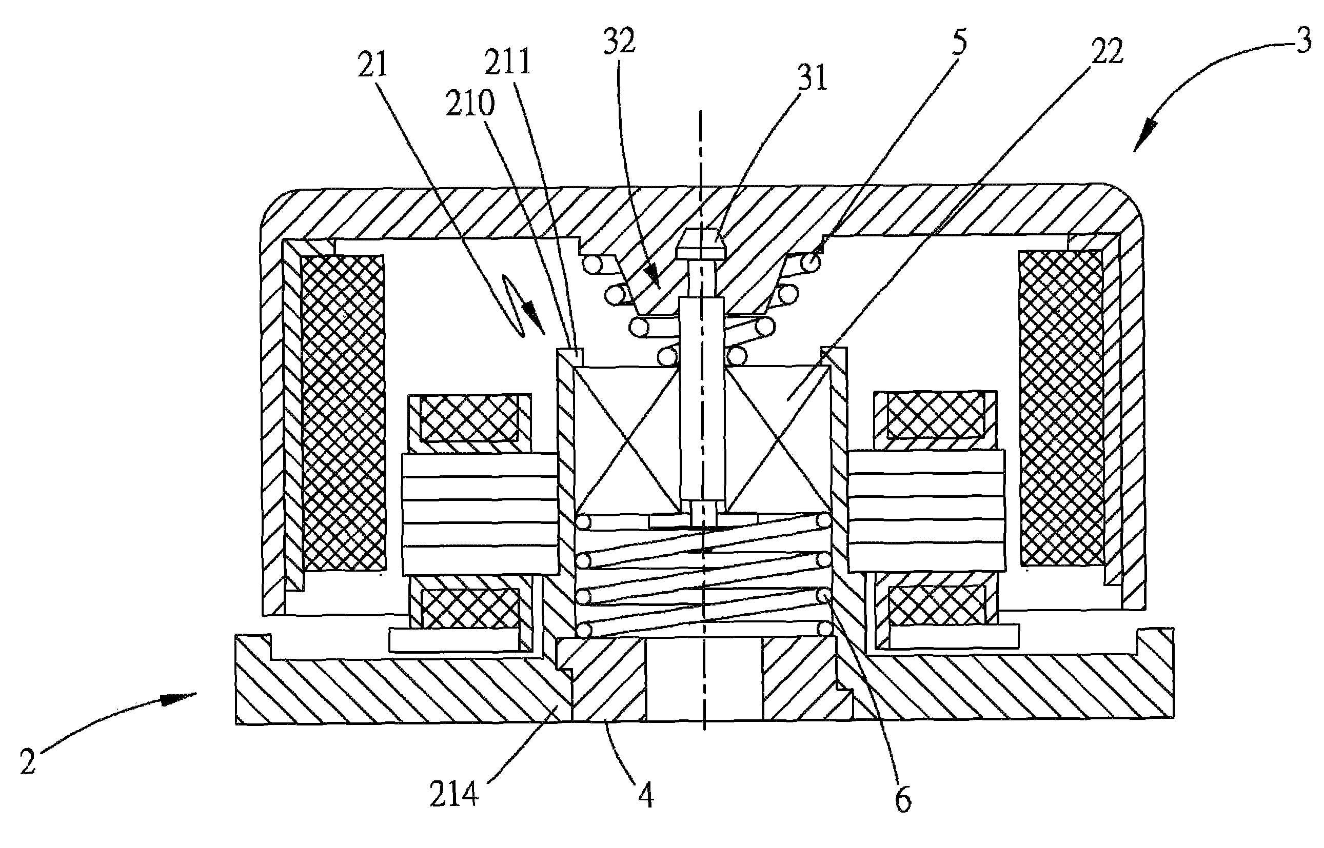
Please refer to FIGS. 2 and 3 that are exploded and assembled sectional views, respectively, of a single-bearing fan structure according to a preferred embodiment of the present invention. As shown, the single-bearing fan structure includes a fan frame 2, a blade hub 3, a retainer 4, a first elastic element 5, and a second elastic element 6. The fan frame 2 includes a bearing cup 21 with a bearing 22 received therein. The bearing cup 21 has a first end 210 and a second end 214. The first end 210 of the bearing cup 21 is provided with a lip portion 211 radially protruded toward a centerline of the bearing cup 21 to abut on the bearing 22. The bearing cup 21 is provided on an inner side at a position adjacent to the second end 214 with a groove 215 for correspondingly engaging with the retainer 4. The bearing 22 is a single ball bearing for supporting blades formed on the blade hub 3 to rotate.

The blade hub 3 includes a rotary shaft 31, which has a proximal end fixedly connected to th...


PUM


Abstract

A single-bearing fan structure includes a fan frame having a bearing cup with a bearing received therein, the bearing cup having a radially inward protruded lip portion formed at a first end to abut on a top of the bearing, and a groove internally formed at a second end; a blade hub having a rotary shaft fixedly connected thereto with a distal end of the rotary shaft inserted into the bearing; a retainer engaged with the groove; a first elastic element fitted around the rotary shaft and located between the blade hub and the bearing; and a second elastic element received in the bearing cup and located between the bearing and the retainer. The first and second elastic elements and the bearing respectively axially and radially support the blade hub, enabling the fan structure to operate stably and have extended service life.

Description

FIELD OF THE INVENTIONThe present invention relates to a fan structure, and more particularly to a single-bearing fan structure that includes first and second elastic elements and one single bearing to respectively provide axial and radial support to a blade hub, enabling the fan structure to have reduced manufacturing cost, stable operation, lowered noise, and extended service life.BACKGROUND OF THE INVENTIONFollowing the developments in different technological fields, more and more finely designed and high-power products have been introduced into the market. However, the high-power products would inevitably produce high temperature during the operation thereof to endanger the products. The electronic elements in the products might become burned-out to cause failed products or even more serious problems. Therefore, most of the precision products are provided with a cooling fan to force away the heat produced by the products during the operation thereof.FIGS. 1A and 1B are exploded ...

Claims


Application Information

Patent Timeline
Patent Type & Authority Patents(United States)
IPC IPC(8): F04D29/059
CPCF04D29/059F04D25/062
Inventor CHEN, MING-JU
Owner ASIA VITAL COMPONENTS(SHEN ZHEN) CO LTD
Why Eureka
Try Eureka