Inference of turbulence hazard from proximity to radar turbulence measurement

a turbulence hazard and radar technology, applied in the direction of instruments, meteorology, clear air turbulence detection/forecasting, etc., can solve the problems that the intensity of high-intensity turbulence experienced by aircraft cannot always be spatially coincident, and aircraft are sensitiv

Active Publication Date: 2011-11-15
HONEYWELL INT INC
View PDF17 Cites 12 Cited by
  • Summary
  • Abstract
  • Description
  • Claims
  • Application Information

AI Technical Summary

Problems solved by technology

However, aircraft are sensitive to the component of turbulent wind in the vertical direction.
High intensities of aircraft-experienced turbulence cannot be expected to always be spatially coincident with high values of radar-measured turbulence.

Method used


Image

  • Inference of turbulence hazard from proximity to radar turbulence measurement
  • Inference of turbulence hazard from proximity to radar turbulence measurement
  • Inference of turbulence hazard from proximity to radar turbulence measurement

Examples


Embodiment Construction

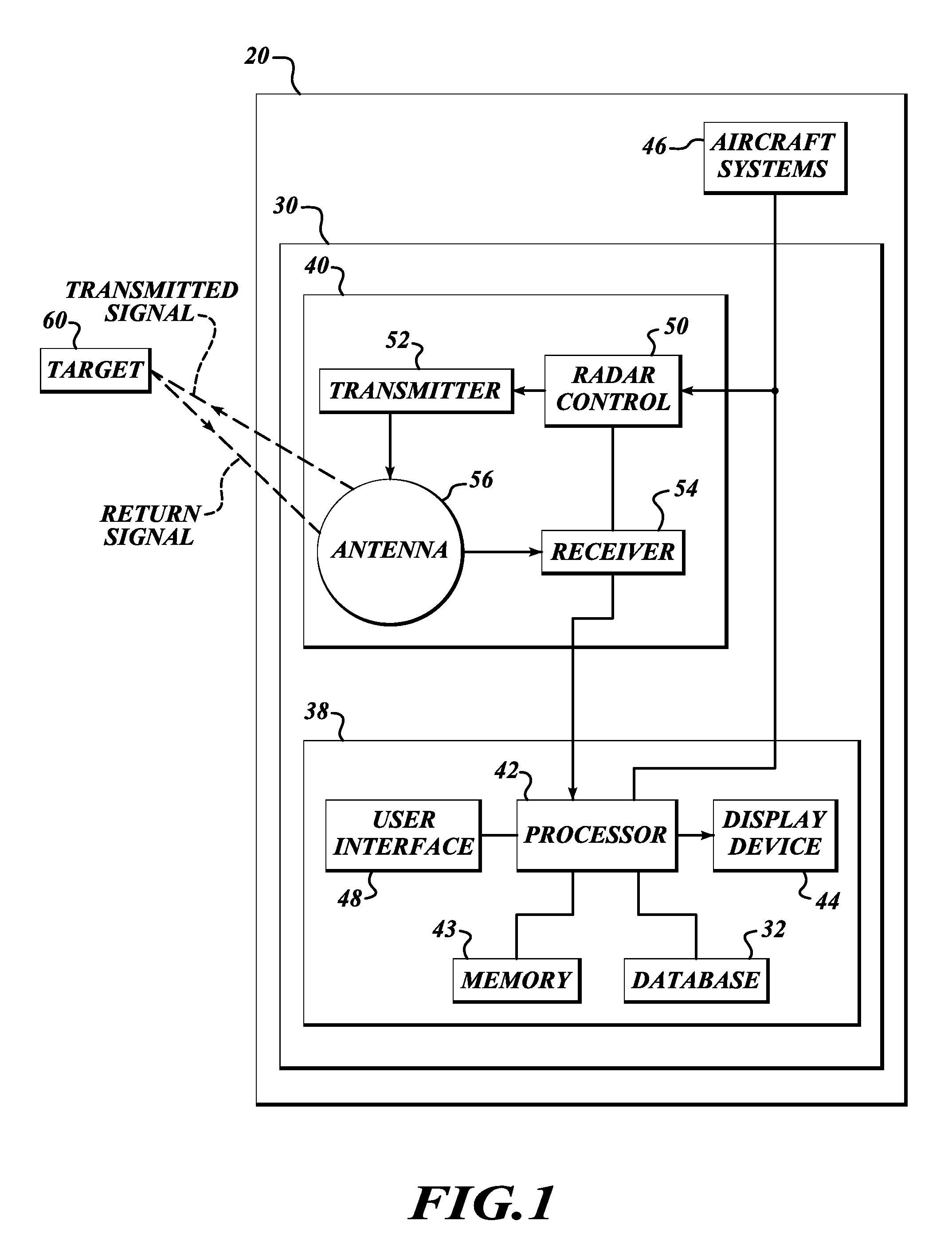
[0009]FIG. 1 illustrates an exemplary aircraft 20 having a weather display system 30 for providing improved radar returns. The exemplary weather display system 30 includes a weather radar system 40 and a display / interface front-end 38, and receives information from an aircraft system 46. The display / interface front-end 38 includes a display processor 42, memory 43, a display device 44, a user interface 48, and a database 32. An example of the radar system 40 includes a radar controller 50 (coupled to the user interface 48), a transmitter 52, a receiver 54, and an antenna 56. The radar controller 50 controls the transmitter 52 and the receiver 54 for performing the sending and receiving of signals through the antenna 56. The weather radar system 40 and the display / interface front-end 38 are electronically coupled to the aircraft system 46.

[0010]Radar relies on a transmission of a pulse of electromagnetic energy, referred to herein as a signal. The antenna 56 narrowly focuses the tran...


PUM


Abstract

Systems and methods for conveying turbulence hazards to a flight crew. An exemplary weather radar system includes a three-dimensional buffer, a processor, and a display. The processor receives weather radar reflectivity values, stores the received weather radar reflectivity values into a three-dimensional buffer, generates and stores turbulence values into cells of the three-dimensional buffer based on the stored respective reflectivity values, and generates first display icons for cells that are located within a predefined threshold distance from a cell in the three-dimensional buffer that has been determined to include a turbulence value that is greater than a first threshold value. The display presents the first display icons when associated cells are selected for display from the three-dimensional buffer.

Description

BACKGROUND OF THE INVENTION[0001]Airborne radar is used to predict where an aircraft might experience excessive turbulence. This information can then be used by pilots to plan routes that avoid the turbulence. The radar can measure the component of turbulence winds only along the direction from the radar to the point in question, which is primarily the horizontal direction. However, aircraft are sensitive to the component of turbulent wind in the vertical direction. High intensities of aircraft-experienced turbulence cannot be expected to always be spatially coincident with high values of radar-measured turbulence.SUMMARY OF THE INVENTION[0002]The present invention provides systems and methods for conveying turbulence hazards to a flight crew. An exemplary weather radar system includes a three-dimensional buffer, a processor and a display. The processor receives and stores turbulence values into cells of the three-dimensional buffer, and generates first display icons for cells that ...

Claims


Application Information

Patent Timeline
Patent Type & Authority Patents(United States)
IPC IPC(8): G01S7/04
CPCG01S13/953G01W1/00G01W2001/003Y02A90/10
Inventor CHRISTIANSON, PAUL
Owner HONEYWELL INT INC
Why Eureka
Try Eureka