Image forming apparatus and method forming a latent image for embedding information in an image

a technology of image forming apparatus and latent image, which is applied in the field of image processing apparatus and a method, can solve the problems of increasing the cost of image processing, becoming a significant social issue, and waste of printed sheets,

Inactive Publication Date: 2011-11-15
SHARP KK
View PDF24 Cites 7 Cited by
  • Summary
  • Abstract
  • Description
  • Claims
  • Application Information

AI Technical Summary

Benefits of technology

[0024]Accordingly, the image containing the latent image is viewed as an image having a uniform shade level so that it is possible to provide the latent image that is hard to recognize by the naked eye. Consequently, even when the information is embedded in the first pattern image, the information can be concealed. Therefore, it becomes unnecessary to provide a camouflage pattern over the image containing the latent image for concealing the information, and such a situation can be avoided that the information embedded in the first pattern is lost due to the camouflage pattern.
[0031]Thereby, in the latent-image-containing image produced based on the mask image by using the first and second pattern images having substantially the same shade level, a smooth change occurs in shade level of a boundary portion between the latent image and the peripheral image. Consequently, it is possible to provide the latent image that is hard to recognize by the naked eye. Particularly, when information is embedded in the first pattern image, it is not necessary to provide a camouflage pattern over the first-pattern image, and such a situation can be avoided that the camouflage pattern causes loss of the information.
[0037]Accordingly, in the latent-image-containing image produced based on the mask image by using the first and second pattern images having substantially the same shade level, a smooth change occurs in shade level of a boundary portion between the latent image and the peripheral image. Consequently, it is possible to provide the latent image that is hard to recognize by the naked eye. When information is embedded in the first pattern image, it is not necessary to provide a camouflage pattern over the first pattern image for concealing the image, and thus such a situation can be prevented that the camouflage pattern causes loss of the information. Further, since the latent image can be produced merely by selectively combining the first and second pattern images, fast processing can be performed.
[0045]Accordingly, the dot-conversion thins the dots in the contour portion so that the number of dots decreases as the position moves toward the outer side of the mask image. Accordingly, by selectively combining the first and second pattern images according to the pixel value (dots) of the mask image, it is possible to change slowly the rate of combination of the first and second pattern images in the contour portion, and it is possible to provide the latent image that is more hard to recognize.
[0052]According to the example embodiment presented herein, the image containing the latent image is viewed as an image having a uniform shade level so that it is possible to provide the latent image that is hard to recognize by the naked eye. Consequently, even when the information is embedded in the first pattern image, the information can be concealed. Therefore, it becomes unnecessary to provide a camouflage pattern over an image containing the latent image for concealing the information, and such a situation can be avoided that the information containing the embedded first pattern is lost due to the camouflage pattern.

Problems solved by technology

Since copy machine technologies have been developed in recent years, it is now possible to copy or counterfeit documents without difficulty and this has become a significant social issue.
When a design of the latent image is changed, new sheets of paper must be prepared, which results in a waste of the printed sheets, and excessively increases a cost.
Further, it is impossible to change the letters to be embedded in response to every printing of the document.
Therefore, the patterns are uniform at a distant view, but a boundary between the coarse and fine patterns becomes conspicuous in a close view, and such a problem occurs that the latent image is readily recognized with the naked eye even when it is not copied.
Since the camouflage pattern is more conspicuous than the boundary between the coarse and fine patterns, it is difficult to recognize the latent image with the naked eye.
However, one can easily recognize a boundary portion between the dot pattern bearing the symbols and the replaced pattern similarly to Japanese Patent Laying-Open Nos. 54-074125 and 07-231384, and a problem that the latent image is visible to the naked eye is not yet overcome.
In this case, the latent image is not conspicuous to the eye, but such a problem arises that the camouflage pattern destroys the dot pattern, and information embedded in the image cannot be read.
As described above, when information is embedded in at least one of the plurality of patterns forming the latent image, a mere combination of the foregoing patent references cannot camouflage the latent image to make it inconspicuous without losing the embedded information.

Method used


Image

  • Image forming apparatus and method forming a latent image for embedding information in an image
  • Image forming apparatus and method forming a latent image for embedding information in an image
  • Image forming apparatus and method forming a latent image for embedding information in an image

Examples


first embodiment

[0095]A first embodiment will now be described with reference to the drawings.

[0096](Function Structure)

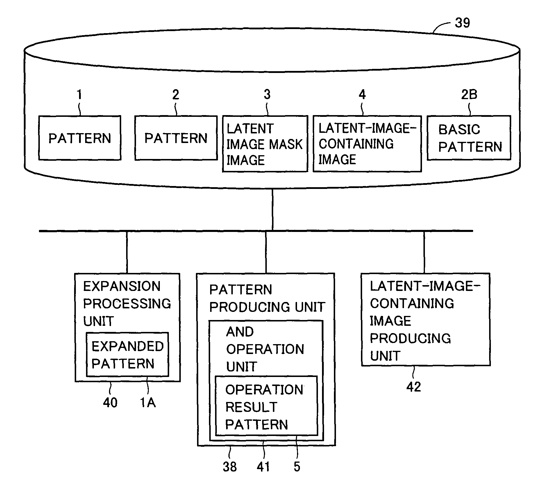
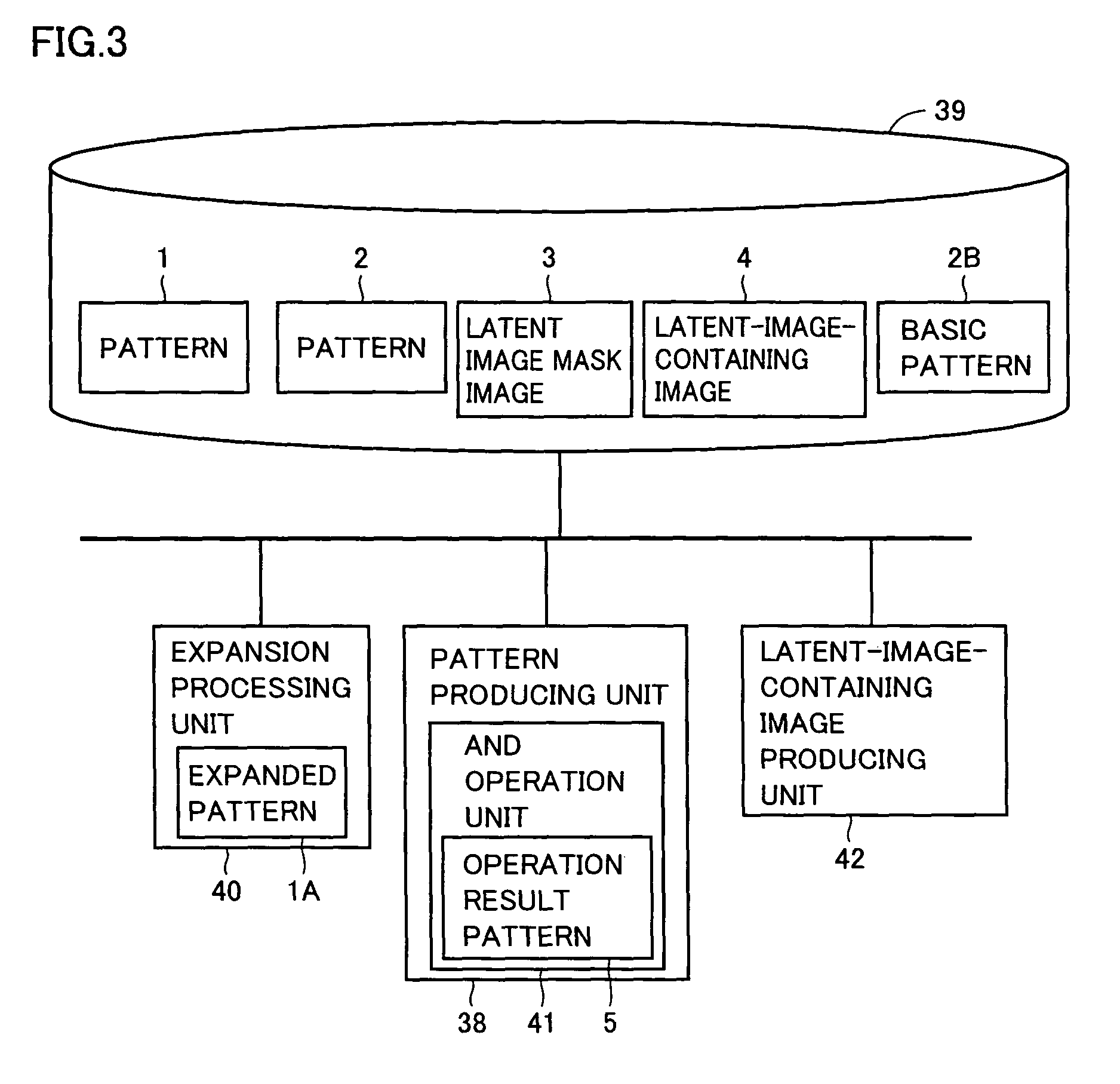
[0097]FIG. 3 shows a function structure according to this embodiment. Referring to FIG. 3, the image processing apparatus according to the embodiment includes a data storing unit 39, an expansion processing unit 40, a pattern producing unit 38 having an AND operation unit 41 and an image producing unit 42 producing a latent-image-containing image, i.e., an image containing a latent image. Data storing unit 39 stores in advance a pattern 1 that is an image data of a dot pattern, a basic pattern 2B that is an image data of a dot pattern and a mask image data 3 for the latent image, and further stores a pattern 2 that is image data of a dot pattern produced by pattern producing unit 38, and data 4 of the latent-image-containing image produced by image producing unit 42. Data storing unit 39 corresponds to a predetermined area in memory 1424 or fixed disk 1426. Pattern producing unit ...

second embodiment

[0116]A second embodiment will now be described with reference to the drawings.

[0117](Function Structure)

[0118]FIG. 12 shows a function structure according to this embodiment. Referring to FIG. 12, an image processing apparatus according to this embodiment includes data storing unit 39, a smoothing processing unit 43, a pseudo shading processing unit 44 and a latent-image-containing image producing unit 45. Data storing unit 39 stores, in advance, patterns 1 and 2A, latent image mask image data 3 and latent-image-containing image data 7 produced by latent-image-containing image producing unit 45. Data storing unit 39 corresponds to a predetermined area in memory 1424 or fixed disk 1426. Smoothing processing unit 43, pseudo shading processing unit 44 and latent-image-containing image producing unit 45 correspond to functions of programs prestored in memory 1424 or fixed disk 1426, and CPU 1412 reads and executes the programs to achieve the functions of the respective units. These uni...

third embodiment

[0141]A third embodiment will now be described with reference to the drawings.

[0142](Function Structure)

[0143]FIG. 18 shows a function structure according to the embodiment. Referring to FIG. 18, the image processing apparatus according to the embodiment includes data storing unit 39, expansion processing unit 40, a dot removing unit 47, an OR operation unit 48 and a latent-image-containing image producing unit 49. Data storing unit 39 prestores patterns 1 and 2A, latent image mask image data 3 and latent-image-containing image data 9 produced by latent-image-containing image producing unit 49. Expansion processing unit 40, dot removing unit 47, OR operation unit 48 and latent-image-containing image producing unit 49 correspond to functions of programs prestored in memory 1424 or fixed disk 1426. CPU 1412 reads and executes the programs to achieve the functions of the respective units. These units may be formed of dedicated circuits.

[0144]Patterns 1 and 2A as well as latent image ma...


PUM


Abstract

A pattern producing unit performs arithmetic on values of pixels corresponding to a pattern and a basic pattern read from a data storing unit with an AND operation unit, and thereby produces a pattern having substantially the same shade level as the pattern. The latent-image-containing image producing unit produces the latent-image-containing image by selectively combining the pattern and the produced pattern according to the values of respective pixels of mask image data read from the data storing unit for producing a latent image.

Description

[0001]This nonprovisional application is based on Japanese Patent Application No. 2005-191028 filed with the Japan Patent Office on Jun. 30, 2005, the entire contents of which are hereby incorporated by reference.BACKGROUND[0002]1. Field of the Technology[0003]The technology presented herein relates to an image processing apparatus and a method, and particularly to an image forming apparatus and a method forming a latent image for embedding information in an image.[0004]2. Background Art[0005]Since copy machine technologies have been developed in recent years, it is now possible to copy or counterfeit documents without difficulty and this has become a significant social issue. Therefore, a latent image printing technique has been proposed as one of techniques that reveal a latent image when copied so that one can identify a reproduction at a first glance.[0006]Japanese Patent Laying-Open No. 54-074125 provides a printed matter in which a latent image is printed in fine dots (i.e., h...

Claims


Application Information

Patent Timeline
Patent Type & Authority Patents(United States)
IPC IPC(8): H04N1/40
CPCG03G21/043H04N1/00838H04N1/00883
Inventor NAKO, KAZUYUKI
Owner SHARP KK
Why Eureka
Try Eureka