Liquid crystal display apparatus

a technology of liquid crystal display and display screen, which is applied in the direction of optics, polarising elements, instruments, etc., can solve the problems of difficult recognition of steps and the screen itself darkening, and achieve the effect of improving the viewability of the apparatus and increasing the difficulty of step recognition

Active Publication Date: 2018-10-11
NITTO DENKO CORP
View PDF25 Cites 3 Cited by
  • Summary
  • Abstract
  • Description
  • Claims
  • Application Information

AI Technical Summary

Benefits of technology

[0011]According to the present invention, in a liquid crystal display apparatus having a step between its display screen and outermost surface, a polarizer on its viewer side is arranged on a side closer to a viewer with respect to the step. Accordingly, while the brightness of the display screen is maintained, the step is made difficult to recognize and hence the viewability of the apparatus can be improved. In one embodiment, so-called λ / 4 plates are further arranged on both sides of the step, and hence the difficulty with which the step is recognized can be more significantly raised.

Problems solved by technology

However, the technology involves a problem in that the display screen itself darkens, though it becomes difficult to recognize the step.

Method used


Image

  • Liquid crystal display apparatus
  • Liquid crystal display apparatus
  • Liquid crystal display apparatus

Examples


example 1

[0113](i) Polarizing Plate Two commercial polarizing plates (manufactured by Nitto Denko Corporation, product name: “CWQ1463VCUHC”) were prepared, and were defined as a first polarizing plate (polarizer) and a second polarizing plate (polarizer).

(ii) Cover Sheet

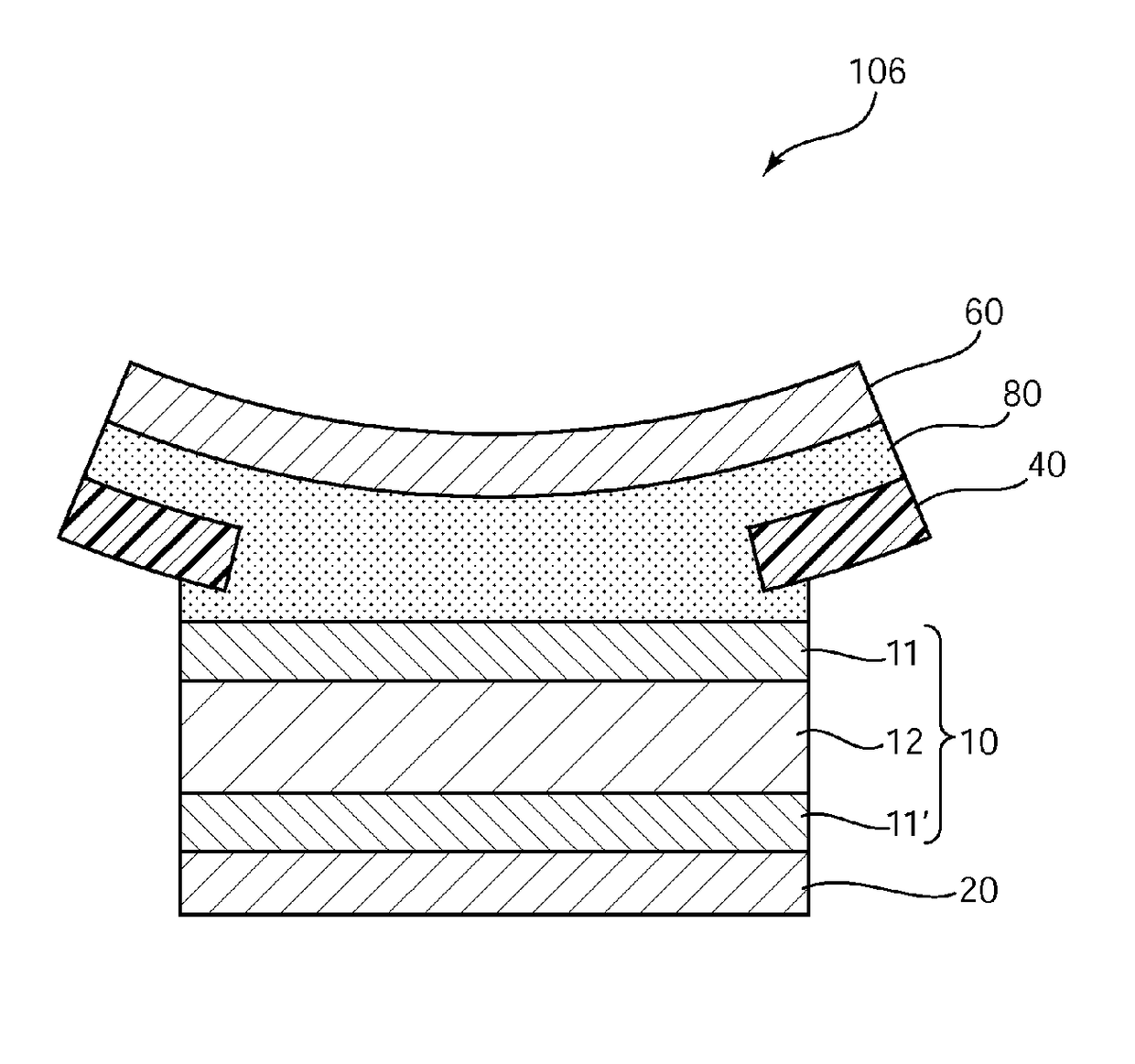
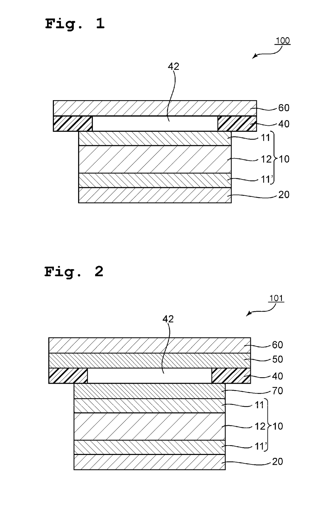
[0114]A commercial methacrylic resin sheet (manufactured by Nitto Jushi Kogyo Co., Ltd., product name: “FLAT N-885”, thickness: 1.0 mm) was used, and its portion corresponding to a display region of a liquid crystal cell to be described later was punched to provide an opening portion.

(iii) Liquid Crystal Cell

[0115]A liquid crystal panel was removed from a product available under the product name “plusone” (IPSmode) from Century Corporation. Further, optical films bonded to the top and bottom of the liquid crystal cell were removed, and the surfaces from which the optical films had been removed were washed. A liquid crystal cell thus obtained was used.

(iv) Production of Liquid Crystal Display Apparatus

[0116]The cover sheet des...

example 2

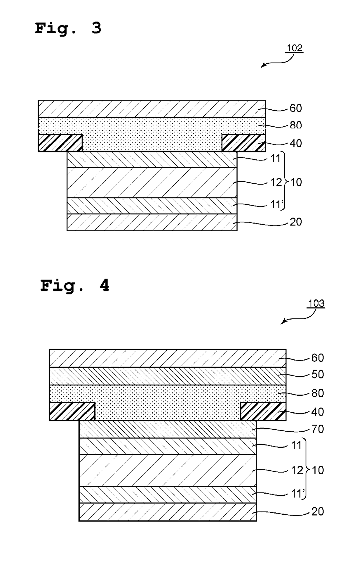
[0117]A liquid crystal display apparatus was produced in the same manner as in Example 1 except that: a first optical compensation layer was further arranged between the second polarizer and the cover sheet; and a second optical compensation layer was further arranged between the cover sheet and the liquid crystal cell. Specifically, the first optical compensation layer and the second optical compensation layer were prepared by using two retardation films produced as described below. Here, the bonding of the respective optical films was performed so that: an angle formed by the slow axis of the first optical compensation layer and the absorption axis of the second polarizer was 450; and the slow axis of the first optical compensation layer and the slow axis of the second optical compensation layer were substantially perpendicular to each other. The resultant liquid crystal display apparatus was subjected to the same evaluations as those of Example 1. The results are shown in Table 1...

example 3

[0119]A liquid crystal display apparatus was produced in the same manner as in Example 1 except that the opening portion of the cover sheet was filled with the pressure-sensitive adhesive. The resultant liquid crystal display apparatus was subjected to the same evaluations as those of Example 1. The results are shown in Table 1.


PUM

PropertyMeasurementUnit
refractive indexaaaaaaaaaa
thickness direction retardationaaaaaaaaaa
angleaaaaaaaaaa

Abstract

There is provided a liquid crystal display apparatus having the following feature: although the liquid crystal display apparatus has a step between its display screen and outermost surface, the step is hardly recognized; and the liquid crystal display apparatus can achieve bright display. A liquid crystal display apparatus according to the present invention includes a liquid crystal cell; a first polarizer arranged on a back surface side of the liquid crystal cell; a cover sheet arranged on a viewer side of the liquid crystal cell, the cover sheet having a transmission portion at a position corresponding to a display region of the liquid crystal cell; and a second polarizer arranged on a viewer side of the cover sheet to cover the transmission portion, wherein an absorption axis direction of the first polarizer and an absorption axis direction of the second polarizer are substantially perpendicular to each other.

Description

TECHNICAL FIELD[0001]The present invention relates to a liquid crystal display apparatus.BACKGROUND ART[0002]A liquid crystal display apparatus has been used in a wide variety of applications including a television, a smart phone, a personal computer monitor, and a digital camera, and the applications have been further expanding. As a result, such forms that the liquid crystal display apparatus is embedded in various structures have been adopted in some applications of the liquid crystal display apparatus. Specific examples of such applications include: an operation information screen in a railway vehicle (e.g., the next-station guide display of a passenger vehicle); display portions, such as various meters and a navigation system arranged in the instrument panel and console of an automobile; various meters of the cockpit of an airplane; and a monitor arranged in a hospital, a security office, a combat information center, or the like. In each of such forms, in response to a demand i...

Claims


Application Information

Patent Timeline
Patent Type & Authority Applications(United States)
IPC IPC(8): G02F1/1335G02F1/13363G02F1/1343
CPCG02F1/133528G02F1/13363G02F1/134309G02F2001/133541G02F2001/133638G02B5/30G02F2413/06G02F2202/28G02F2201/38G02F1/133308G02F1/133331G02F1/133541G02F1/133562G02F1/133637G02F1/133638
Inventor TAKADA, KATSUNORISUEFUSA, EIKOKITAMURA, YOSHITSUGUKIMURA, KEISUKEUMEMOTO, SEIJI
Owner NITTO DENKO CORP
Why Eureka
Try Eureka