Connector assembly having a compensation circuit component

a technology of compensation circuit and connector assembly, which is applied in the direction of connection, electrical apparatus, coupling device connection, etc., can solve the problems of electrical connectors being more susceptible to performance degradation, electrical connectors not without problems, and the solution of problems has not yet been found

Active Publication Date: 2011-11-22
TYCO ELECTRONICS LOGISTICS AG (CH)
View PDF12 Cites 32 Cited by
  • Summary
  • Abstract
  • Description
  • Claims
  • Application Information

AI Technical Summary

Problems solved by technology

However, such electrical connectors are not without problems.
For instance, as the throughput speed of such electrical connectors increases, the electrical connectors are more susceptible to performance degradation.
Such solutions have heretofore proven difficult.
However, such electrical connectors have reliability problems.
For example, the solder joint between the passive circuit element and the signal conductors is subject to damage during the life of the connector, such as from loading, shock, thermal mismatch between the copper signal conductors and the mounting contacts of the passive circuit elements, and the like.

Method used


Image

  • Connector assembly having a compensation circuit component
  • Connector assembly having a compensation circuit component
  • Connector assembly having a compensation circuit component

Examples


Embodiment Construction

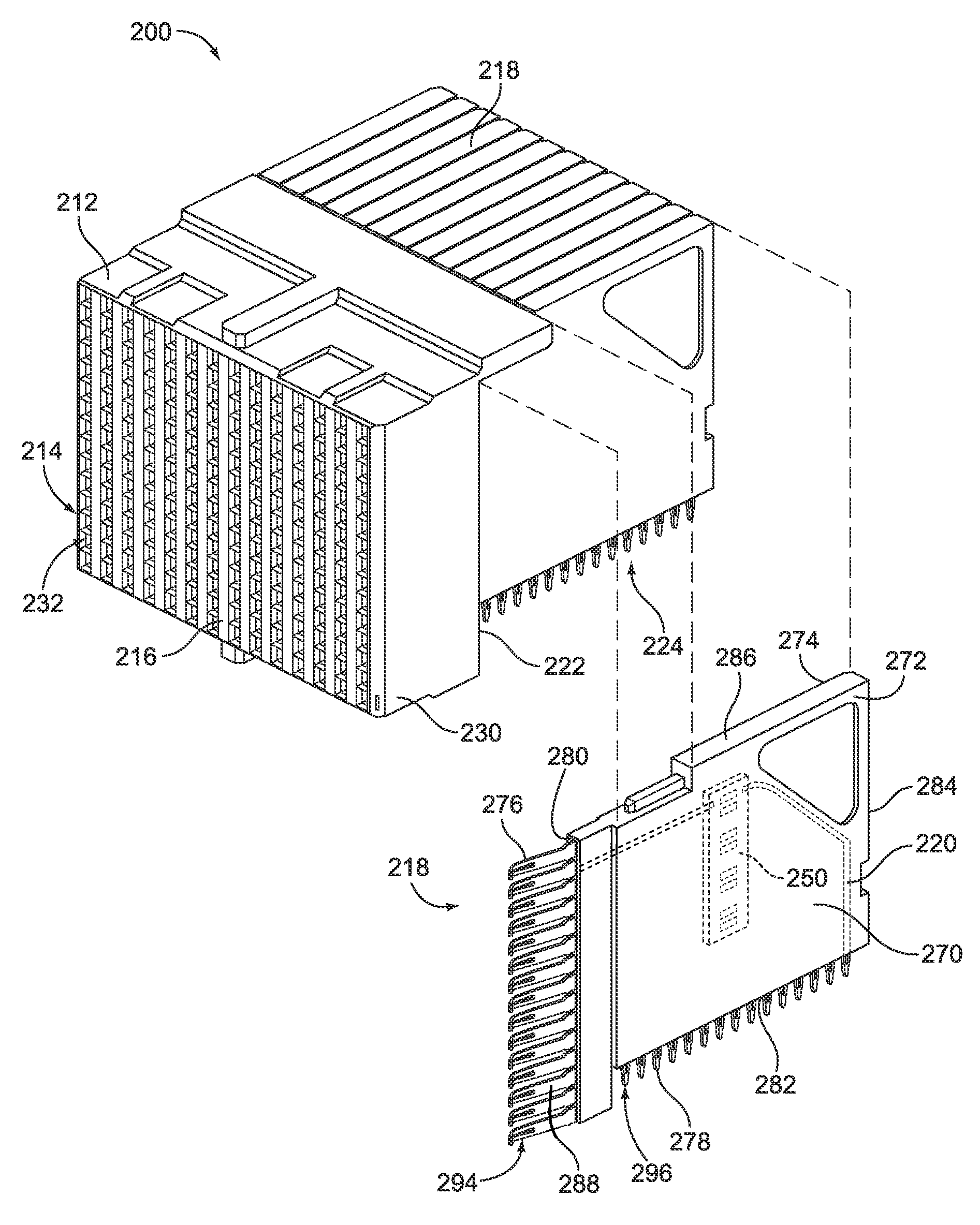
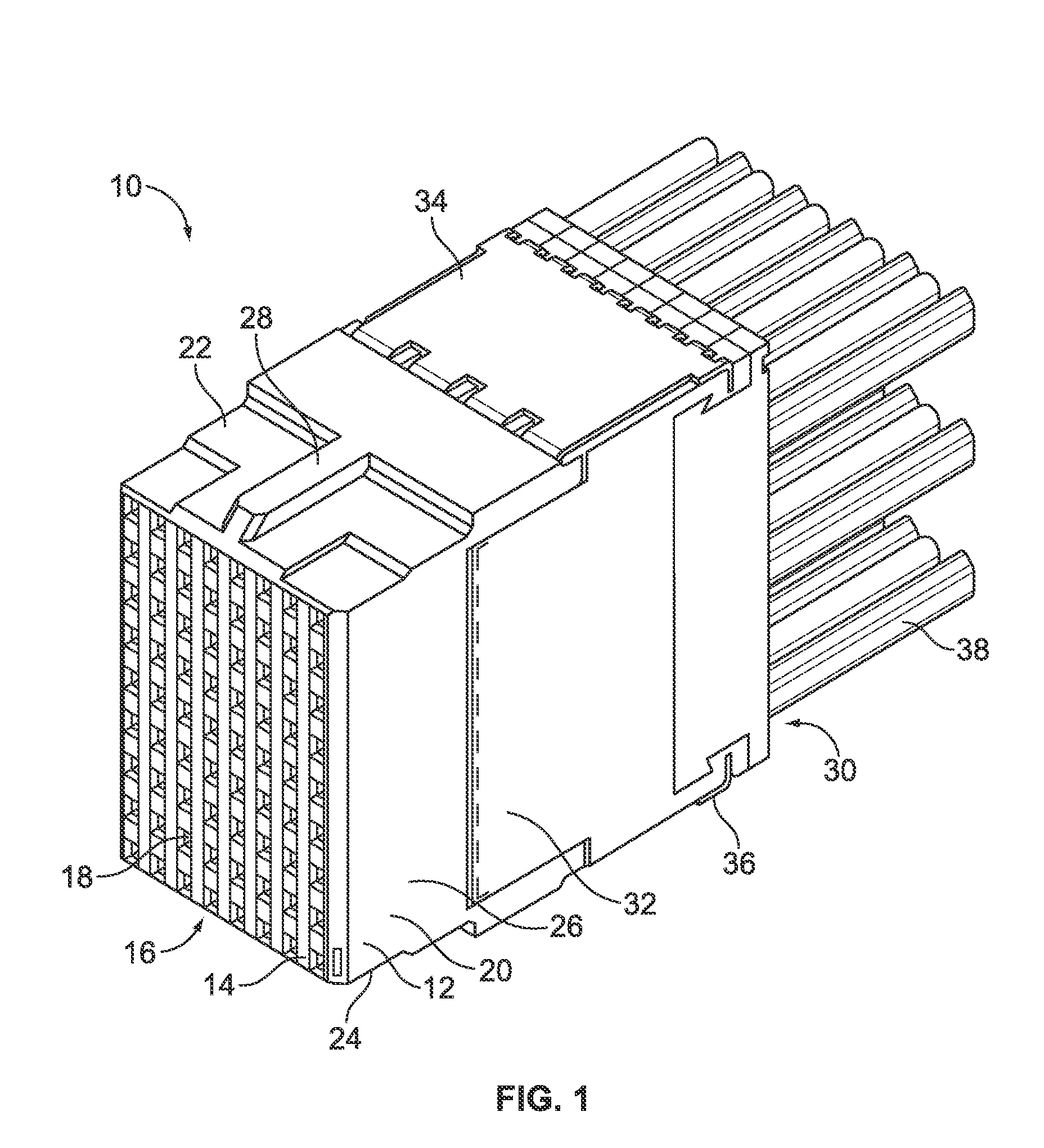
FIG. 1 is a front perspective view of a receptacle connector assembly 10 formed in accordance with an exemplary embodiment. The receptacle connector assembly 10 is matable with a header connector assembly (not shown) to create a differential connector system. For example, the header connector assembly may be a Z-PACK TinMan header connector, which is commercially available from Tyco Electronics. The receptacle connector assembly 10 constitutes a high speed, differential cable connector, however the benefits herein described are also applicable to other connectors in alternative embodiments, such as board mounted connectors, such as the receptacle connector assembly 200 (shown in FIG. 3).

As illustrated in FIG. 1, the receptacle connector assembly 10 includes a dielectric housing 12 having a forward mating end 14 that includes a mating interface 16 and a plurality of contact cavities 18. The contact cavities 18 are configured to receive corresponding mating contacts (not shown) from t...


PUM


Abstract

A connector assembly includes a contact module with a lead frame having signal conductors defining separate conductive paths. The contact module also includes a compensation circuit component coupled to the leadframe. The compensation circuit component has a substrate and multiple compensation circuit elements mounted to the substrate, where the substrate is coupled to the leadframe such that the compensation circuit elements are electrically connected to corresponding signal conductors. The contact module also includes a body encasing the signal conductors and the compensation circuit component.

Description

BACKGROUND OF THE INVENTIONThe subject matter herein relates generally to connector assemblies, and more particularly, to connector assemblies having electrical compensation components.With the ongoing trend toward smaller, faster, and higher performance electrical components such as processors used in computers, routers, switches, etc., it has become increasingly desirable for the electrical interfaces along the electrical paths to also operate at higher frequencies and at higher densities with increased throughput. For example, performance demands for video, voice and data drive input and output speeds of connectors within such systems to increasingly faster levels.Electrical connectors typically are arranged to be connected to complementary connector halves to form connector pairs. One application environment that uses such electrical connectors is in high speed, differential electrical connectors, such as those common in the telecommunications or computing environments. In a tra...

Claims


Application Information

Patent Timeline
Patent Type & Authority Patents(United States)
IPC IPC(8): H01R13/66
CPCH01R13/6473H01R12/724H01R13/518H01R13/6587H01R13/6625H01R13/6633
Inventor JEON, MYOUNGSOOTAYLOR, ATTALEE SNARRCONSOLI, JOHN JOSEPH
Owner TYCO ELECTRONICS LOGISTICS AG (CH)
Why Eureka
Try Eureka