Storage device module and screw mounting structure of the same

a technology of storage device module and screw mounting structure, which is applied in the direction of bolts, record information storage, lighting support devices, etc., can solve the problem that the screw of the storage device module is easily los

Inactive Publication Date: 2011-11-22
HONG FU JIN PRECISION IND (SHENZHEN) CO LTD +1
View PDF8 Cites 23 Cited by
  • Summary
  • Abstract
  • Description
  • Claims
  • Application Information

AI Technical Summary

Benefits of technology

[0005]The installation of a hard disk drive in a computer typically involves the use of screws to attach the hard disk drive to a bracket to form a storage device module, which is extractably mounted in a computer chassis. However, the screws of the storage device module are easily lost.

Problems solved by technology

However, the screws of the storage device module are easily lost.

Method used


Image

  • Storage device module and screw mounting structure of the same
  • Storage device module and screw mounting structure of the same
  • Storage device module and screw mounting structure of the same

Examples


Embodiment Construction

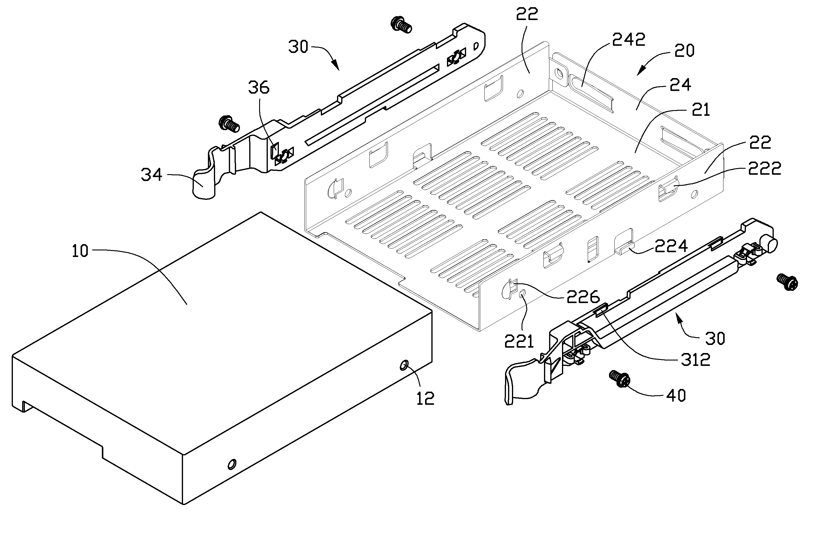
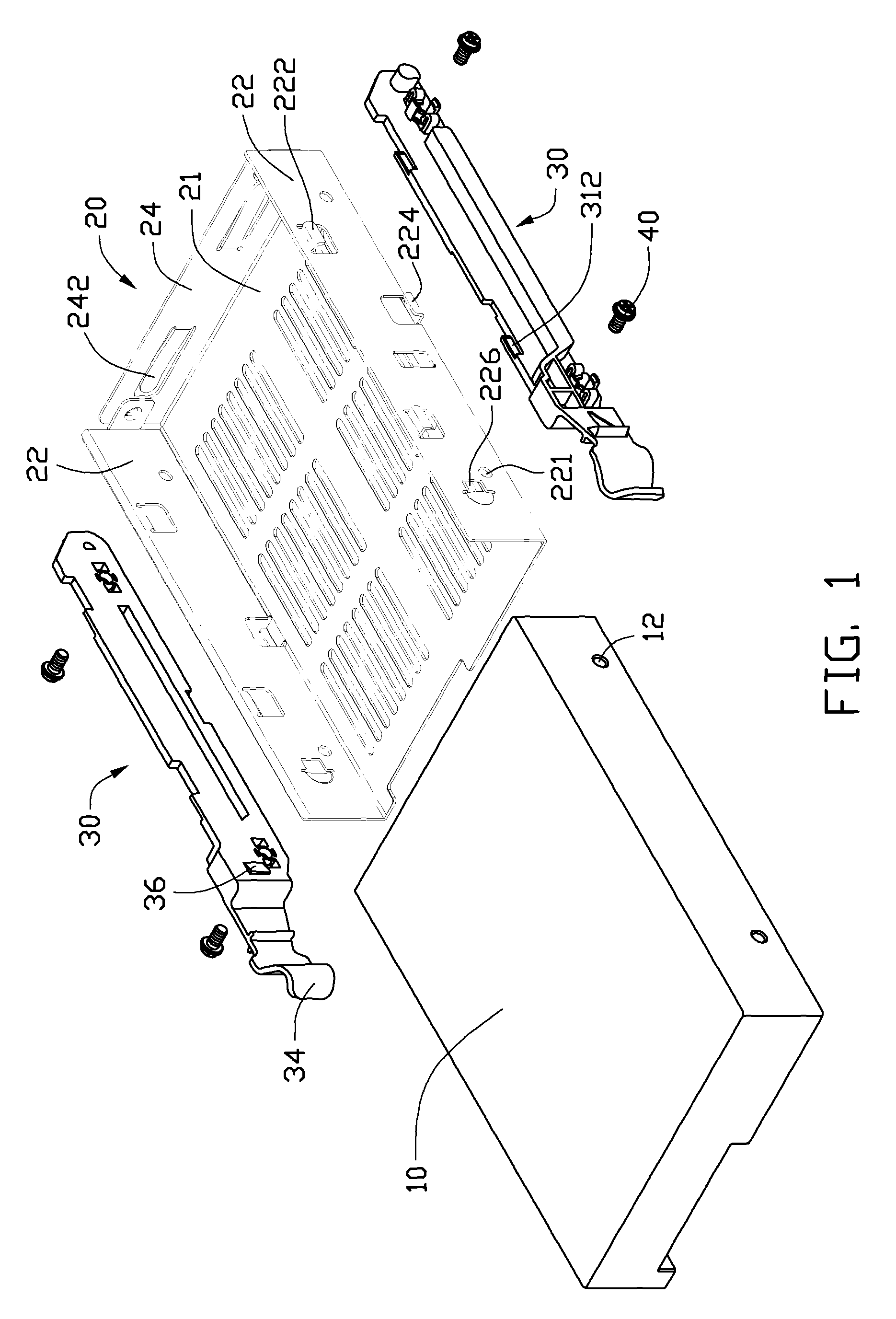
[0011]Referring to FIG. 1, an exemplary embodiment of a storage device module includes a storage device 10, a bracket 20 for receiving the storage device 10, two mounting members 30 attached to opposite sides of the bracket 20 respectively, and a plurality of screws 40. A plurality of mounting holes 12 is defined in opposite sides of the storage device 10.

[0012]The bracket 20 includes a bottom wall 21, two sidewalls 22 perpendicularly extending up from opposite sides of the bottom wall 21, and an end wall 24 perpendicularly extending up from one end of the bottom wall 21 and connecting to the sidewalls 22. The sidewalls 22 are parallel to each other. A plurality of long slots is defined in the bottom wall 21 for heat dissipating. Each sidewall 22 defines a plurality of through holes 221 corresponding to the mounting holes 12 of the storage device 10. Two L-shaped first locating tabs 222 extend from an upper portion of an outer surface of each sidewall 222 towards a lower portion of ...


PUM


Abstract

A storage device module is disclosed. The storage device module includes a storage device, a bracket for receiving the storage device, a mounting member attached to one side of the bracket, and a screw attached to the mounting member for extending through the bracket to screw into the storage device. A screw mounting structure is arranged on the mounting member for retaining the screw.

Description

BACKGROUND[0001]1. Technical Field[0002]The present invention relates to storage device modules and, more particularly, to a data storage device module with a screw mounting structure.[0003]2. Description of Related Art[0004]An electronic apparatus, such as a desktop computer, tower computer, server, or the like, usually includes storage devices, such as hard disk drives, compact disk read-only memory (CD-ROM) drives, digital video disc (DVD) drives, floppy disk drives, and the like. These storage devices are typically added to increase the functionality of the electronic apparatus as desired by a user.[0005]The installation of a hard disk drive in a computer typically involves the use of screws to attach the hard disk drive to a bracket to form a storage device module, which is extractably mounted in a computer chassis. However, the screws of the storage device module are easily lost.BRIEF DESCRIPTION OF THE DRAWINGS[0006]FIG. 1 is an exploded, isometric view of an exemplary embodi...

Claims


Application Information

Patent Timeline
Patent Type & Authority Patents(United States)
IPC IPC(8): G06F1/16E05C5/04F16B41/00F16B37/04A47F7/00A47B81/00
CPCG06F1/187G11B33/124H05K7/1418Y10T403/1683Y10T292/1099Y10T70/5867
Inventor ZHANG, GUANG-YIZHANG, ZHEGUO, BING-BAO
Owner HONG FU JIN PRECISION IND (SHENZHEN) CO LTD
Why Eureka
Try Eureka