Premixed combustion burner for gas turbine

a combustion burner and gas turbine technology, applied in the combustion process, hot gas positive displacement engine plants, lighting and heating apparatus, etc., can solve problems such as possible increase in nox, and achieve the effect of substantially uniform fuel gas flow rate and prevention of flashback

Active Publication Date: 2011-11-29
MITSUBISHI POWER LTD
View PDF20 Cites 26 Cited by
  • Summary
  • Abstract
  • Description
  • Claims
  • Application Information

AI Technical Summary

Benefits of technology

In consideration of the circumstance described above, an object of the present invention is to provide a premixed combustion burner for a gas turbine that can efficiently premix fuel and air to produce fuel gas having a uniform concentration, while reliably achieving prevention of flash back by making the flow rate of fuel gas substantially uniform.
According to the present invention, fuel and air can be efficiently premixed to produce fuel gas having a uniform concentration, and an effect of reliable prevention of flash back can be achieved by making the flow rate of the fuel gas substantially uniform.

Problems solved by technology

However, since a total amount of fuel injected into the air passageway per unit time does not change, the fuel concentration in another area (for example, the area on the outer circumference side of the air passageway) increases inversely to the reduction made in the fuel concentration on the inner circumference side of the air passageway, and flame temperature rises on the downstream side, resulting in a possible increase in NOx.

Method used


Image

  • Premixed combustion burner for gas turbine
  • Premixed combustion burner for gas turbine
  • Premixed combustion burner for gas turbine

Examples


first embodiment

Hereinafter, a premixed combustion burner of a gas turbine according to the present invention is described, with reference to the drawings.

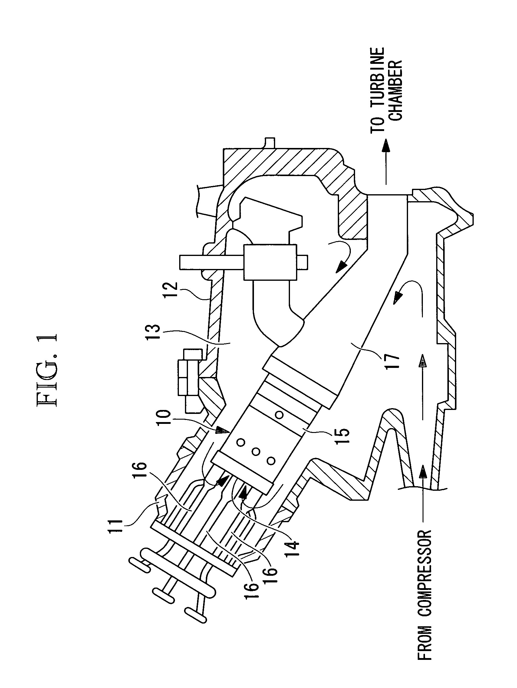
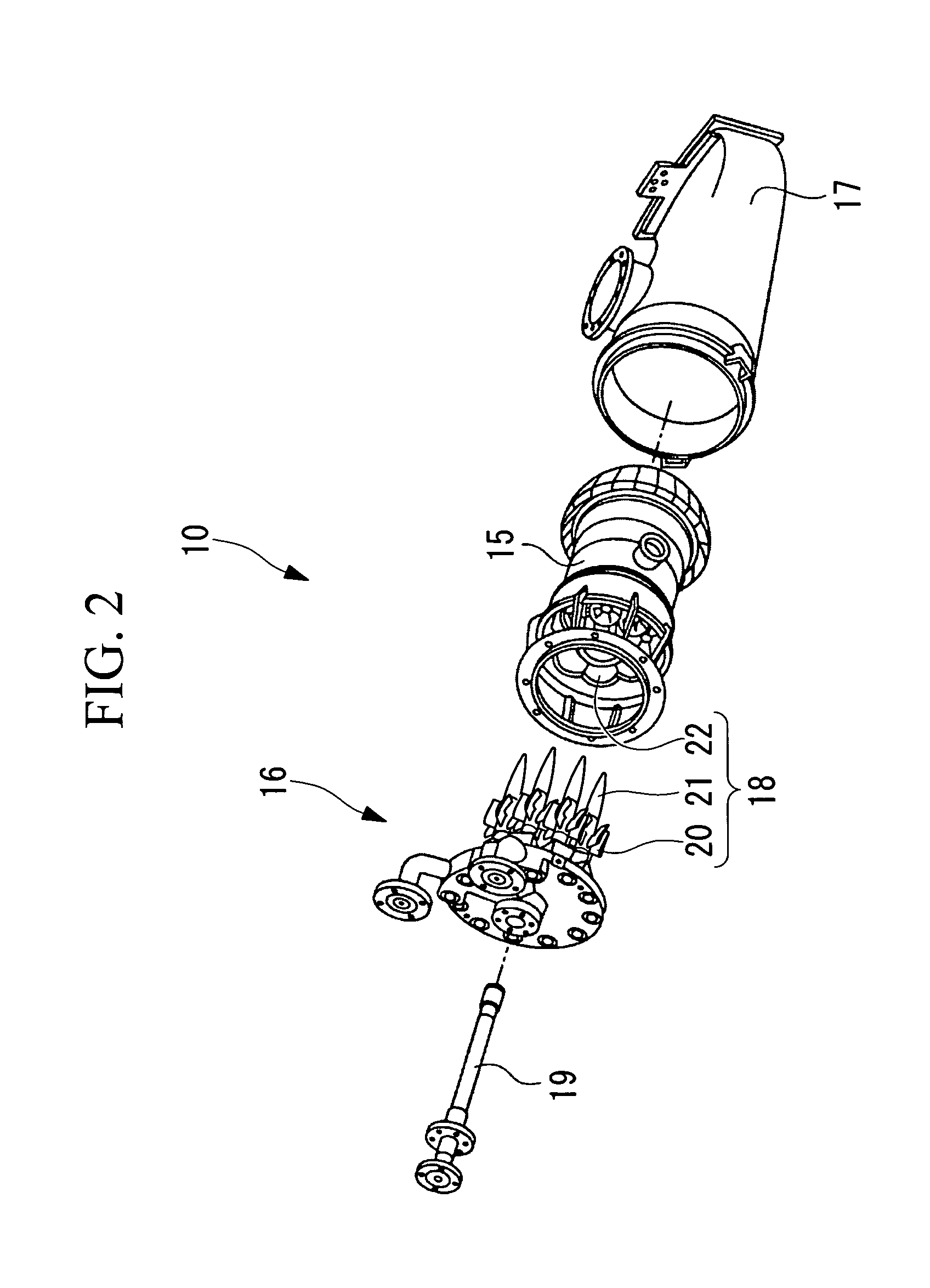
In FIG. 1, a gas turbine (not shown in the diagram) provided with a premixed combustion burner for a gas turbine (hereinafter, referred to as “premixed combustion burner”) 18 (refer to FIG. 2) according to the present invention and used for a generator or the like, is constructed with principal members including a compressor (not shown in the diagram), a combustor 10, and a turbine (not shown in the diagram). Many gas turbines have a plurality of combustors, and air compressed by the compressor and fuel supplied into the combustor 10 are mixed and are combusted within each combustor 10 to generate combustion gas at high temperature. This high temperature combustion gas is supplied to the turbine to drive the rotation of the turbine.

As shown in FIG. 1, a plurality of the combustors 10 of the gas turbine is arranged in a ring shape inside a combust...

third embodiment

the premixed combustion burner according to the present invention is described, with reference to FIG. 7.

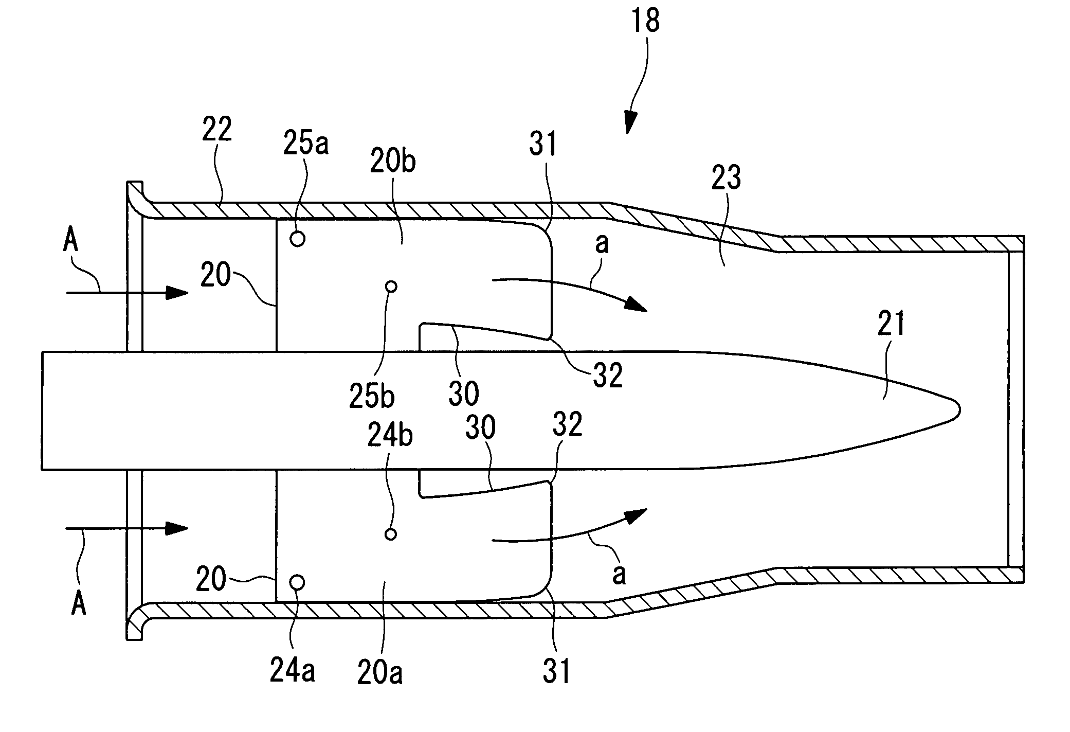
A premixed combustion burner 38 according to the present embodiment differs from the premixed combustion burner of the first embodiment in that a clearance (gap) 50 is provided between an outer circumference side end surface (tip) of each of the swirler vanes 20 and an inner surface of the burner cylinder 22. Since other components are the same as those in the first embodiment, descriptions thereof are omitted here.

The clearance 50 is provided in an area from the front edge to the rear edge of each of the swirler vanes 20, and its length C in the vane height direction is respectively set equal to the height h of the cutaway section 30, that is, 3% to 20% (preferably approximately 15%) of the maximum vane height H of the swirler vane 20.

Incidentally, the pressure on the vane back side surface 20a of the swirler vane 20 is low, and the pressure on the vane front side surface 20b is...

fourth embodiment

the premixed combustion burner according to the present invention is described, with reference to FIG. 8.

A premixed combustion burner 48 according to the present embodiment differs from the aforementioned premixed combustion burner of the third embodiment in that injection holes 44a, 44b, 45a and 45b are provided instead of the injection holes 24a, 24b, 25a and 25b. Since other components are the same as those in the third embodiment, descriptions thereof are omitted here.

The injection holes 44a and 44b are formed on one surface (the surface on the same side as the vane back side surface 20a of the swirler vane 20) of a peg (fuel injection device) 43, and the injection holes 45a and 45b are formed in the other surface (the surface on the same side as the vane front side surface of the swirler vane 20) of the peg 43. As shown in FIG. 8, the injection holes 44a and 45a are provided on the outer circumference side (radial direction outer side: side further from the fuel nozzle 21) of t...


PUM


Abstract

A premixed combustion burner for a gas turbine can efficiently premix fuel and air to produce fuel gas having a uniform concentration, while reliably achieving prevention of flash back by making the flow rate of fuel gas substantially uniform. The premixed combustion burner for a gas turbine has a fuel nozzle, a burner cylinder arranged so as to surround the fuel nozzle and form an air passageway between itself and the fuel nozzle, and swirler vanes that are arranged along an axial direction of the fuel nozzle in a plurality of positions around the circumferential direction of an outer circumference surface of the fuel nozzle. The swirler vanes gradually curve from an upstream side to a downstream side to spin the air traveling within the air passageway from the upstream side to the downstream side. A cutaway section is provided in a rear edge section on an inner circumference side of the swirler vanes.

Description

BACKGROUND OF THE INVENTION1. Field of the InventionThe present invention relates to a premixed combustion burner for a gas turbine. The present invention is devised so that fuel and air can be efficiently premixed to produce fuel gas having a uniform concentration, while achieving reliable prevention of flash back (back fire) by making the flow rate of fuel gas substantially uniform.2. Description of Related ArtAs a premixed combustion burner for a gas turbine, for example, the premixed combustion burner disclosed in Japanese Translation of a PCT International Application, Publication No. 2006-500544 is commonly known.The invention disclosed in the above patent document is to prevent flash back by lowering the fuel concentration on an inner circumference side (radial direction inner side) of an air passageway.However, since a total amount of fuel injected into the air passageway per unit time does not change, the fuel concentration in another area (for example, the area on the oute...

Claims


Application Information

Patent Timeline
Patent Type & Authority Patents(United States)
IPC IPC(8): F02C1/00
CPCF23R3/14F23R3/286
Inventor ISHIZAKA, KOICHIKAWATA, YUTAKATAKIGUCHI, SATOSHITANIMURA, SATOSHI
Owner MITSUBISHI POWER LTD
Why Eureka
Try Eureka