Radar apparatus and method for forming reception beam of the same

a technology of radar apparatus and antenna, which is applied in direction finders using radio waves, multi-channel direction-finding systems using radio waves, instruments, etc., can solve the problems of limiting the use of airplanes to enlarge the aperture of a relatively large active phased array antenna, and the performance of scanning rate is not advantageous over the active-type antenna

Active Publication Date: 2011-11-29
KK TOSHIBA
View PDF45 Cites 6 Cited by
  • Summary
  • Abstract
  • Description
  • Claims
  • Application Information

AI Technical Summary

Problems solved by technology

However, in comparison with a conventional passive antenna, the active phased arraying of the antenna device necessitates an increase in device size such as dimensions and mass as a circuit configuration has become complicated.
However, there is a limit for use in airplane to enlarge an aperture of a relatively large-sized active phased array antenna.
However, since the passive-type antenna of the large aperture may not perform high-rate beam scanning, the performance in a scanning rate has no advantage over the active-type antenna.
Meanwhile, the method for protruding the radome toward the lower part of the airplane body to accommodate the antenna in the radome poses a limit for enlarging the aperture of the antenna due to restriction on mounting, and it is necessary to repair the airplane body on a large scale, so that the problem of expenses is produced.
As mentioned above, in the conventional radar apparatus, in a case in which there is a limitation in an installation place because the radar apparatus is mounted on a mobile object, since it is hard to enhance the performance and enlarge the aperture of the antenna device, it is also hard to actualize the improvement of the performance of the radar.

Method used


Image

  • Radar apparatus and method for forming reception beam of the same
  • Radar apparatus and method for forming reception beam of the same
  • Radar apparatus and method for forming reception beam of the same

Examples


Embodiment Construction

[0023]The following will describe embodiments of the invention in detail with reference to the drawings.

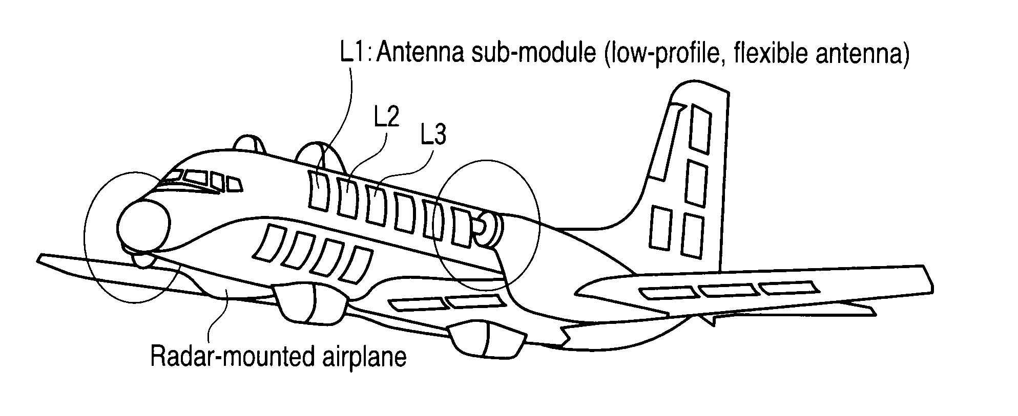
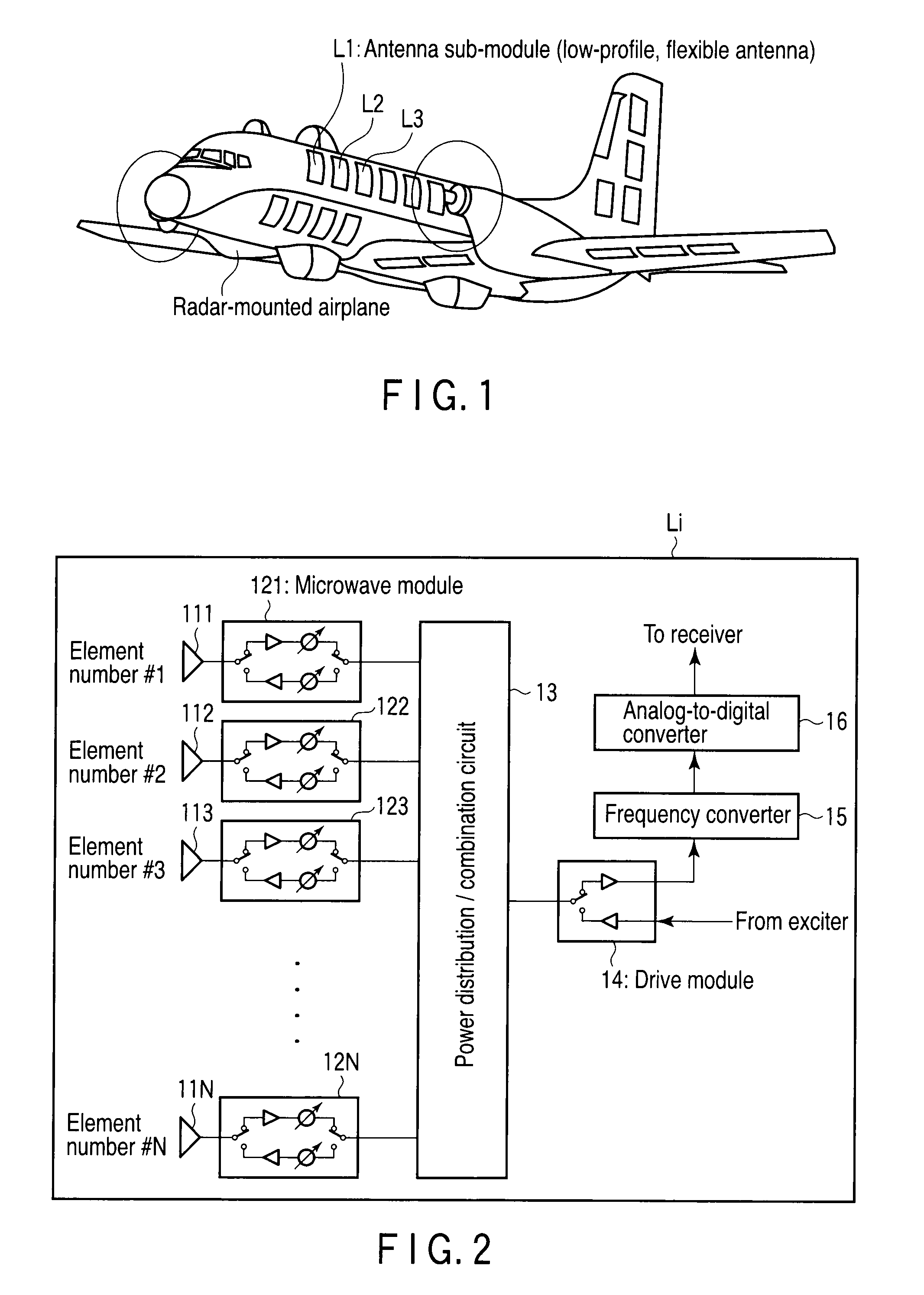
[0024]FIG. 1 shows a perspective view illustrating an antenna mounting image of an airplane A on which a radar apparatus of the invention is mounted. In FIG. 1, the airplane body surface of the airplane A is provided with each low-profile and flexible transmission / reception array antenna, which individually functions an active phased array antenna. A plurality of antenna sub-modules L1-Ln, which function as an active phased array antenna in all, are mounted on arbitrary positions.

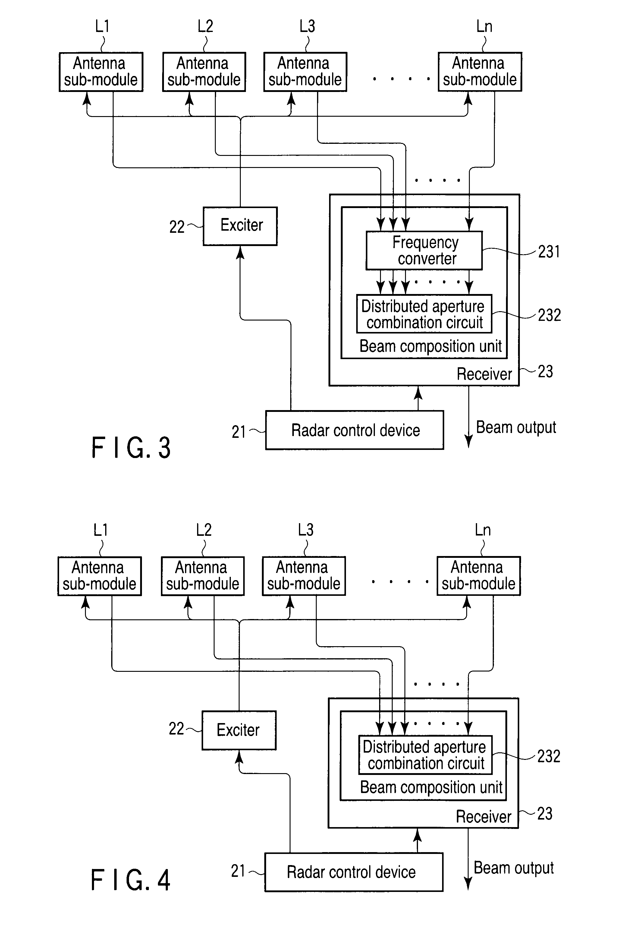
[0025]These antenna sub-modules Li (i are 1 to n) each include, as shown in FIG. 2, N antenna elements (element numbers #1-#N) 111-11N; microwave modules 121-12N which selectively switch excitation and reception of each element 111-11N and compensate each phase and amplitude of transmission signals and reception signals; a power distribution / combination circuit 13 which power-distributes excitation signal...


PUM


Abstract

When an excitation signal is generated from an exciter due to an activation signal generated from a radar control device and is distributed to supply to each antenna sub-module, a combination reception signal is transmitted to a receiver from each antenna sub-module. The receiver takes in the combination reception signal obtained by each sub-module in response to an instruction from the radar control device, a frequency converter converts the combination reception signal into a prescribed frequency band, and a distributed aperture combination circuit performs a beam combination in accordance with a distributed aperture combination algorithm. In this way, a radar apparatus, which is equivalent to an active phased array radar of a large aperture and with high performance, is achieved.

Description

CROSS-REFERENCE TO RELATED APPLICATIONS[0001]This application is based upon and claims the benefit of priority from prior Japanese Patent Application No. 2008-173865, filed Jul. 2, 2008, the entire contents of which are incorporated herein by reference.BACKGROUND OF THE INVENTION[0002]1. Field of the Invention[0003]The present invention relates to a radar apparatus using an active-type antenna device which is mounted on a mobile object such as an airplane and is formed by using an airplane shape to a maximum extent, and relates to a method for forming a reception beam of the radar apparatus.[0004]2. Description of the Related Art[0005]In recent years, in an antenna device of a radar mounted on an airplane, with the enhancement of requirements for higher performance of the radar, requirements for active phased arraying having high function and high performance have become increased. However, in comparison with a conventional passive antenna, the active phased arraying of the antenna ...

Claims


Application Information

Patent Timeline
Patent Type & Authority Patents(United States)
IPC IPC(8): G01S13/00G01S13/74H01Q1/28G01S13/08
CPCG01S3/74G01S7/2813H01Q1/288H01Q3/26H01Q3/30H01Q21/0025G01S2013/0254
Inventor NAKADA, TAIHEISUZUKI, JUNICHIROSATAKE, YOSHIAKI
Owner KK TOSHIBA
Why Eureka
Try Eureka