
Radar antenna array surface fault detection method and system

A radar antenna array and fault detection technology, which is applied in the radar field, can solve the problem that the detection method cannot meet the antenna array fault detection requirements of active phased array radar, and does not comprehensively consider fault diversity and uncertain fault connections. Comprehensive analysis of characteristics and fault characteristics, etc., to achieve broad application value and market prospects, assist radar fault analysis and fault prediction

Active Publication Date: 2018-10-30
BEIJING INST OF RADIO MEASUREMENT
View PDF4 Cites 6 Cited by
  • Summary
  • Abstract
  • Description
  • Claims
  • Application Information

AI Technical Summary

Problems solved by technology

[0003] At present, in engineering, the fault detection of the antenna array of active phased array radar is more based on a single fault characteristic quantity, and all fault characteristic quantities have not been comprehensively analyzed, and the diversity and uncertainty of faults have not been considered comprehensively. Due to the complexity of the connection between nature and various faults, the current detection methods cannot meet the fault detection requirements of the antenna array of active phased array radar.

Method used


Image

  • Radar antenna array surface fault detection method and system
  • Radar antenna array surface fault detection method and system
  • Radar antenna array surface fault detection method and system

Examples


Embodiment Construction

[0028] The principles and features of the present invention will be described below in conjunction with the accompanying drawings, and the examples given are only used to explain the present invention, and are not intended to limit the scope of the present invention.

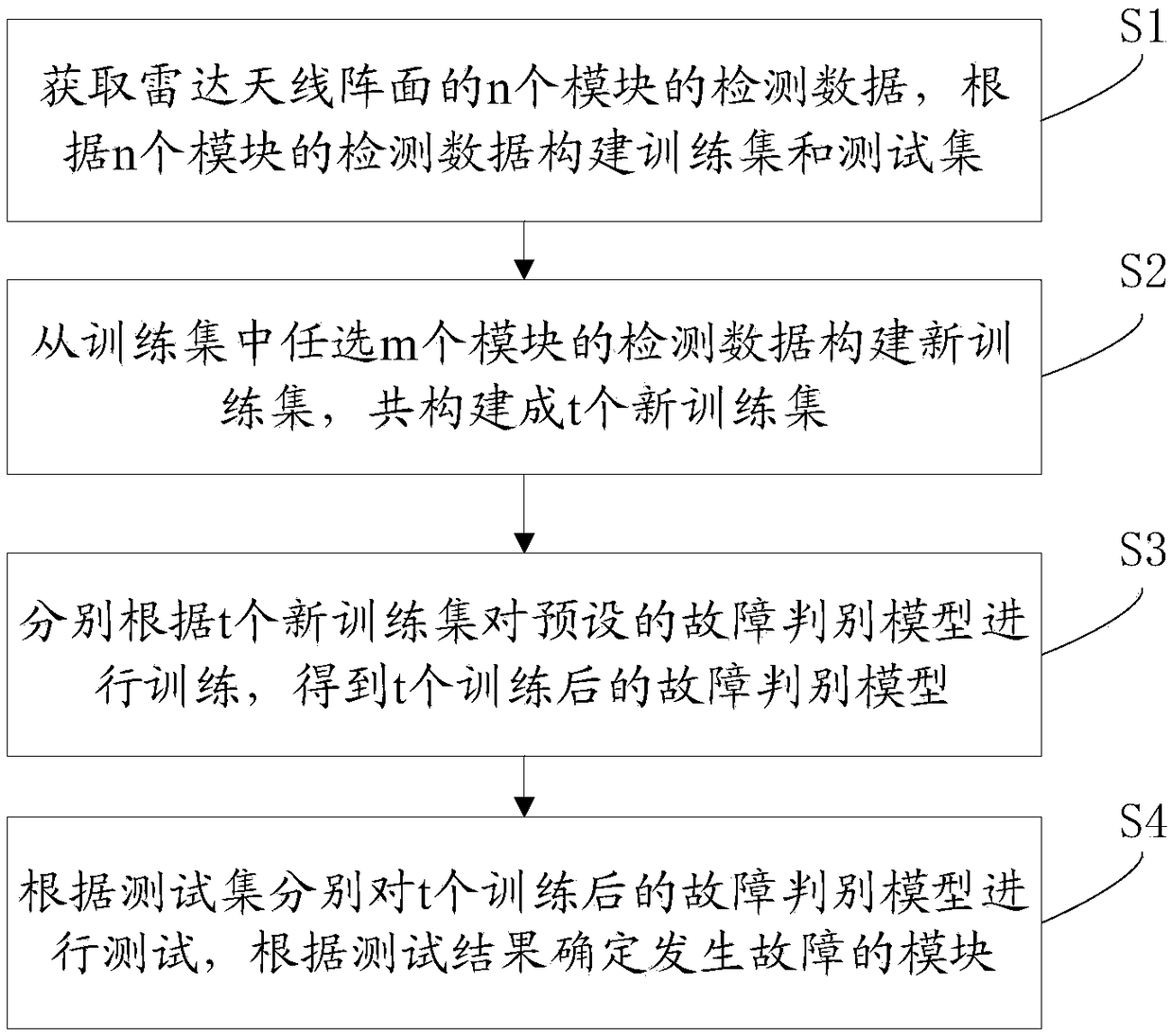
[0029] Such as figure 1 As shown, it is a schematic flow chart provided for an embodiment of a radar antenna array fault detection method of the present invention, which can be used for radar antenna arrays that combine multiple modules and multiple subsystems, such as active phased array radars. Fault detection, the method comprising:

[0030] S1. Obtain detection data of n modules of the radar antenna front, and construct a training set and a test set according to the detection data of n modules.

[0031] It should be noted that these modules are components of the radar antenna array, and are used to monitor various parameters of the radar antenna array and obtain various detection data of the radar antenna a...


PUM


Abstract

The invention discloses a radar antenna array surface fault detection method and a radar antenna array surface fault detection system, and relates to the field of radars. The method comprises the steps of building a training set and a test set according to detected data of n modules; randomly selecting the detected data of m modules from the training set to build new training sets, wherein the t new training sets are jointly built; separately training a preset fault judgment model according to the t new training sets, thus acquiring t trained fault judgment models; and separately testing the trained fault judgment model according to the test set, and determining the faulted module according to a test result. According to the method and system provided by the invention, the detected data ofthe multiple modules of the radar antenna array surface is analyzed in a unified manner, the defect of the analysis method that only uses a single fault characteristic quantity is overcome, the faultcan be quickly and conveniently positioned, the radar fault analysis and fault prediction are effectively assisted, the fault detection requirement of the antenna array surface of the active phased array radar can be met, and the wide application value and the market prospect are achieved.

Description

technical field [0001] The invention relates to the field of radar, in particular to a radar antenna array fault detection method and system. Background technique [0002] For the antenna array of active phased array radar, because it combines multiple modules and subsystems, the operating conditions are complex. When a fault occurs, there are many influencing factors. The same fault may have different manifestations, and The same fault phenomenon may also be the result of several faults working together. [0003] At present, in engineering, the fault detection of the antenna array of active phased array radar is more based on a single fault characteristic quantity, and all the fault characteristic quantities have not been comprehensively analyzed, and the diversity and uncertainty of faults have not been considered comprehensively. Due to the complexity of the connection between nature and various faults, the current detection methods cannot meet the fault detection requir...

Claims


Application Information

Patent Timeline
IPC IPC(8): G06F17/50G01R29/10
CPCG01R29/10G06F30/20
Inventor 董博葛勍张然张艳龚宬张剑
Owner BEIJING INST OF RADIO MEASUREMENT
Learn More