Electronic timepiece with internal antenna

an electronic timepiece and internal antenna technology, applied in loop antennas with ferromagnetic cores, instruments, horology, etc., can solve the problems of increasing the size of the end cap module accordingly, affecting the formation of the timepiece, and easy damage to the amorphous thin film, so as to improve the antenna characteristics

Active Publication Date: 2011-12-06
SEIKO EPSON CORP
View PDF11 Cites 12 Cited by
  • Summary
  • Abstract
  • Description
  • Claims
  • Application Information

AI Technical Summary

Benefits of technology

With consideration for the foregoing problems, an electronic timepiece with an internal antenna according to the present invention improves the antenna characteristics without making the timepiece large.
By laminating a plurality of magnetic members in a stack, this aspect of the invention increases the thickness of the magnetic member and can thus collect even more magnetic flux lines. The flux collection effect is thus improved and antenna performance is further improved.

Problems solved by technology

With the configuration of the related art that attaches an end cap to both ends of the laminated core part of the antenna as described in Japanese Unexamined Patent Appl. Pub. JP-A-2005-269234, the end caps increase the size of the timepiece module accordingly and interfere with forming the timepiece thinner and smaller.
Furthermore, a problem with the configuration that affixes an amorphous thin film to the core as described in Japanese Unexamined Patent Appl. Pub. JP-A-2007-184894 is that the amorphous thin film becomes easily damaged when shock is applied to the timepiece.
Damage to the thin film can be prevented by additionally providing a support member, but providing such a support member also increases the size of the timepiece.

Method used


Image

  • Electronic timepiece with internal antenna
  • Electronic timepiece with internal antenna
  • Electronic timepiece with internal antenna

Examples


embodiment 1

Preferred embodiments of the present invention are described below with reference to the accompanying figures. Note that parts that are functionally the same as parts that have already been described are identified by the same reference numerals, and further description thereof is omitted.

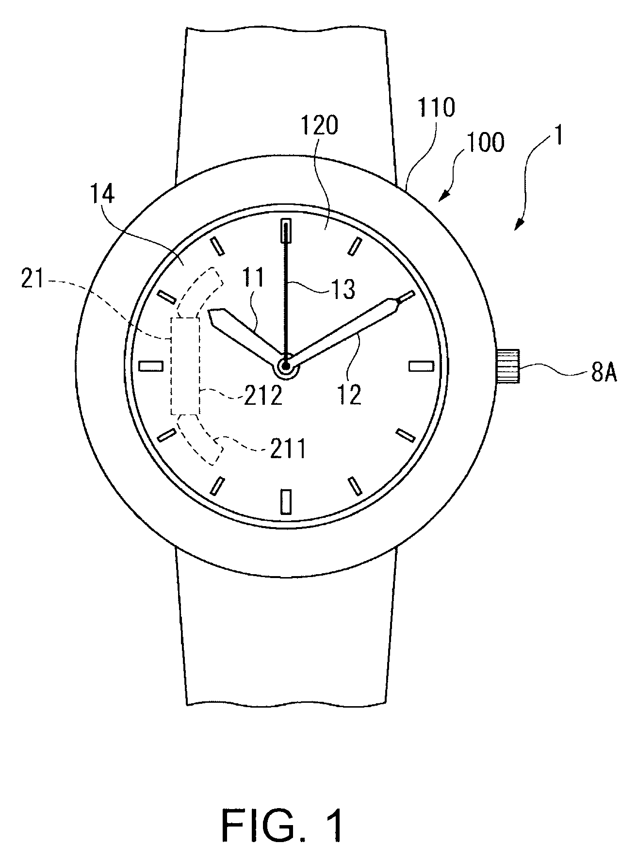
FIG. 1 is a front view of a radio-controlled timepiece as an example of an electronic timepiece with an internal antenna according to a preferred embodiment of the invention.

As shown in FIG. 1, a radio-controlled timepiece 1 according to a preferred embodiment of the invention is an analog timepiece with hands 11, 12, and 13 and a dial 14, and is a timepiece that can receive long-wave standard time signals as external radio frequency information containing time information, and can correct the positions indicated by the hands 11, 12, and 13 based on the received time information.

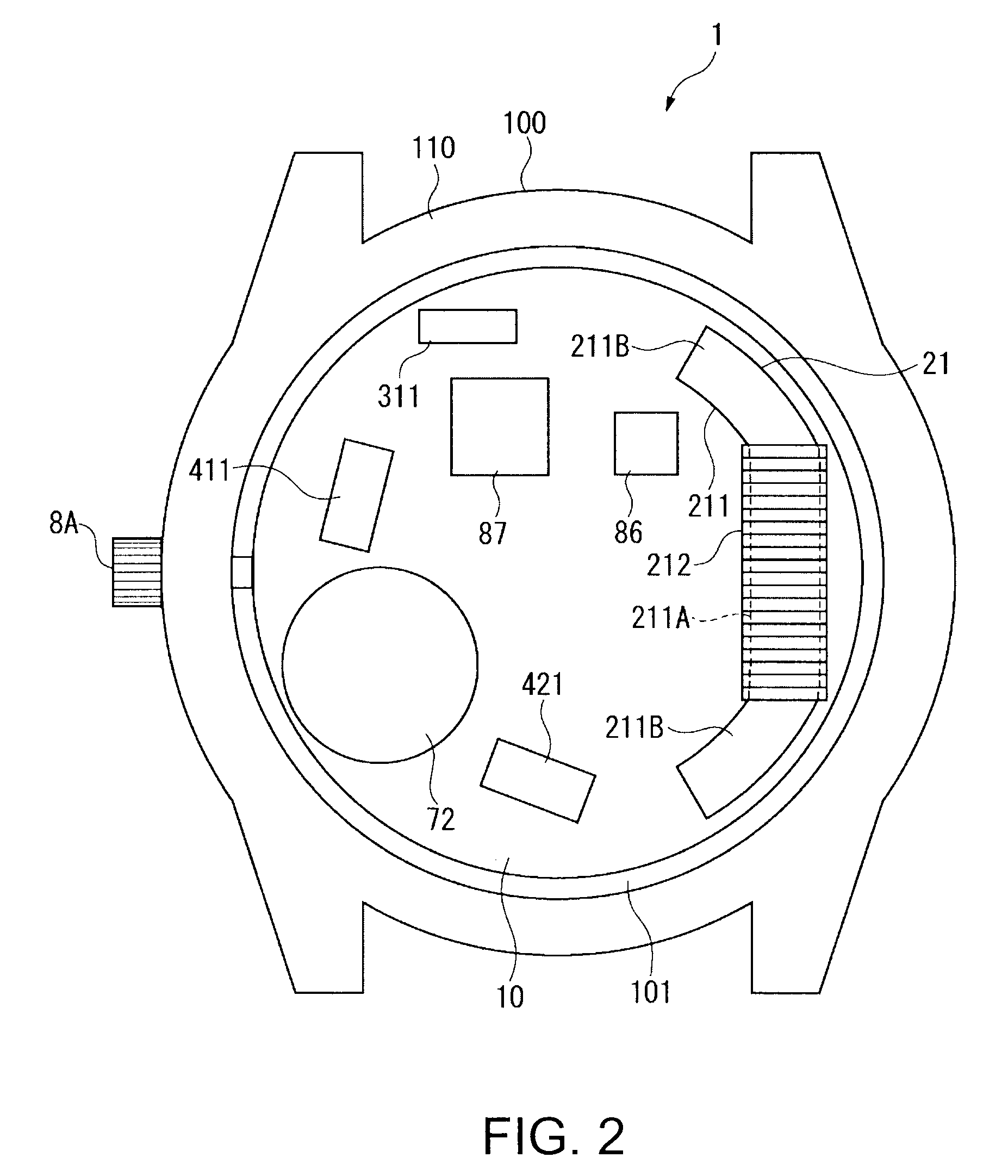
The radio-controlled timepiece 1 includes the hands 11, 12, and 13, the dial 14, a module 10 (see FIG. 2) including compo...

embodiment 2

A second embodiment of the invention is described next with reference to the accompanying figures. Note that in the figures and embodiments described below parts that are the same as in the radio-controlled timepiece 1 according to the first embodiment described above are identified by the same reference numerals, and further description thereof is simplified or omitted.

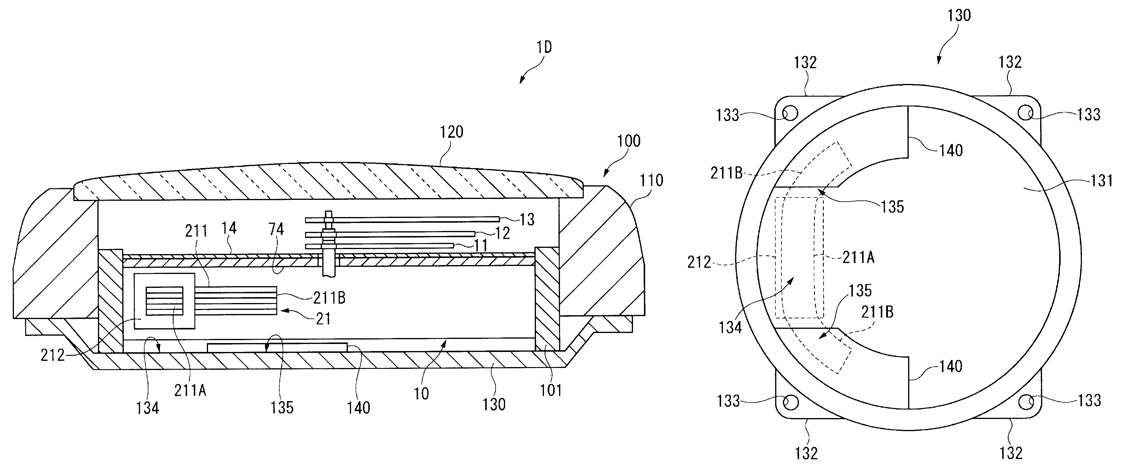
FIG. 9 is a section view of a radio-controlled timepiece according to a second embodiment of the invention through a position near the lead part of the antenna.

The radio-controlled timepiece 1A according to this second embodiment of the invention has plural layers of the amorphous foil members 140 positioned on the base plate 102 in the first embodiment.

More specifically, a plurality of amorphous foil members 140 are layered on the base plate 102 of the radio-controlled timepiece 1A according to the second embodiment of the invention at a position that is not superposed to the coil-overlapping area 104 and is superpo...

embodiment 3

A third embodiment of the invention is described next with reference to the accompanying figures. Note that in the figures and embodiments described below parts that are the same as in the radio-controlled timepiece 1 according to the first embodiment described above are identified by the same reference numerals, and further description thereof is simplified or omitted.

FIG. 10 is a section view through a position near the lead part of the antenna in a radio-controlled timepiece according to a third embodiment of the invention.

In the radio-controlled timepiece 1A according to the second embodiment described above, the amorphous foil layer 141 is formed by stacking the amorphous foil members 140 on the dial-side surface 103 of the base plate 102. In a radio-controlled timepiece 1B according to this third embodiment, however, the amorphous foil members 140 are stacked towards the lead part 211B side.

More specifically, as shown in FIG. 10, a through-hole 102B communicating the dial-side...


PUM


Abstract

An electronic timepiece with an internal antenna has an antenna that has an elongated magnetic core formed from a magnetic body and a coil wound around the magnetic core, and can receive external wireless information, the magnetic core having a coil winding part to which the coil is wound in the lengthwise center part of the magnetic core, and a pair of lead parts extending from both ends of the coil winding part; a module that houses the antenna and processes the external wireless information; and a magnetic member that is positioned with a predetermined gap between the magnetic member and the lead part at a position that is not superposed on a coil-overlapping area that overlaps the coil winding part of the antenna and is superposed on at least a part of a lead-overlapping area that overlaps the pair of lead parts when the electronic timepiece with internal antenna is viewed in plan view from the timepiece thickness direction of the electronic timepiece with internal antenna.

Description

CROSS-REFERENCE TO RELATED APPLICATIONSJapanese Patent application Nos. 2008-027890 filed Feb. 7, 2008, 2008-121655 file May 7, 2008, and 2008-121656 filed May 7, 2008 are hereby incorporated by reference in their entirety.BACKGROUND1. Field of InventionThe present invention relates to an electronic timepiece with an internal antenna enabling receiving external radio frequency signals through the antenna.2. Description of Related ArtElectronic timepieces with an internal antenna are known from the literature. Typical of such timepieces is a radio-controlled timepiece that receives external radio frequency signals carrying time information from an external source and uses this information to adjust the time kept by the timepiece. In order to improve antenna performance in this type of electronic timepiece with an internal antenna, Japanese Unexamined Patent Appl. Pub. JP-A-2005-269234 and Japanese Unexamined Patent Appl. Pub. JP-A-2007-184894 teach configurations that improve the flu...

Claims


Application Information

Patent Timeline
Patent Type & Authority Patents(United States)
IPC IPC(8): H01Q7/08G04C11/02G04G21/04G04R60/12
CPCG04G21/04H01Q1/273G04R60/12
Inventor MIYAHARA, FUMIAKI
Owner SEIKO EPSON CORP
Why Eureka
Try Eureka