Plasma uniformity control by gas diffuser curvature

a technology of gas diffuser and uniformity control, which is applied in the direction of plasma technique, coating, chemical vapor deposition coating, etc., can solve the problems of higher deposition rate, more problematic film thickness and property uniformity control of large area plasma-enhanced chemical vapor deposition (pecvd), and increase the deposition rate. , to achieve the effect of improving thickness uniformity and film property uniformity

Active Publication Date: 2011-12-13
APPLIED MATERIALS INC
View PDF217 Cites 247 Cited by
  • Summary
  • Abstract
  • Description
  • Claims
  • Application Information

AI Technical Summary

Benefits of technology

[0017]Embodiments of a gas distribution plate for distributing gas in a processing chamber are provided. In one embodiment, a gas distribution plate assembly for a plasma processing chamber comprises a diffuser plate having an upstream side and a downstream side, gas passages passing between the upstream and downstream sides of the diffuser plate and hollow cathode cavities at the downstream side of the gas passages. The downstream side of the diffuser plate has a curvature to improve the thickness uniformity and film property uniformity of thin films deposited by PECVD. In one aspect, either the hollow cathode cavity volume density, hollow cathode cavity surface area density, or the cathode cavity density of the diffuser increases from the center of the diffuser to the edge of the diffuser. In another aspect, the downstream side of the gas diffuser plate is divided into a number of concentric zones, wherein the gas passages in each zone are identical and the density, volume, or surface area of hollow cathode cavities of gas passages in each zone gradually increases from the center to the edge of the diffuser plate.
[0018]In another embodiment, a plasma processing chamber comprises a diffuser plate having an upstream side and a downstream side, gas passages passing between the upstream and downstream sides of the diffuser plate and hollow cathode cavities at the downstream side of the gas passages. The down-stream side of the diffuser plate has a curvature to improve the thickness uniformity and film property uniformity of thin films deposited by PECVD. In one aspect, either the hollow cathode cavity volume density, hollow cathode cavity surface area density, or the cathode cavity density of the diffuser increases from the center of the diffuser to the edge of the diffuser.

Problems solved by technology

As the size of substrates continues to grow in the TFT-LCD industry, film thickness and film property uniformity control for large area plasma-enhanced chemical vapor deposition (PECVD) becomes an issue.
As the size of substrates continues to grow in the TFT-LCD industry, especially when the substrate size is at least about 1000 mm by about 1200 mm (or about 1,200,000 mm2), film thickness and property uniformity for large area plasma-enhanced chemical vapor deposition (PECVD) becomes more problematic.
Examples of noticeable uniformity problems include higher deposition rates and more compressive films in the central area of large substrates for some high deposition rate SiN and α-Si films.

Method used


Image

  • Plasma uniformity control by gas diffuser curvature
  • Plasma uniformity control by gas diffuser curvature
  • Plasma uniformity control by gas diffuser curvature

Examples


Embodiment Construction

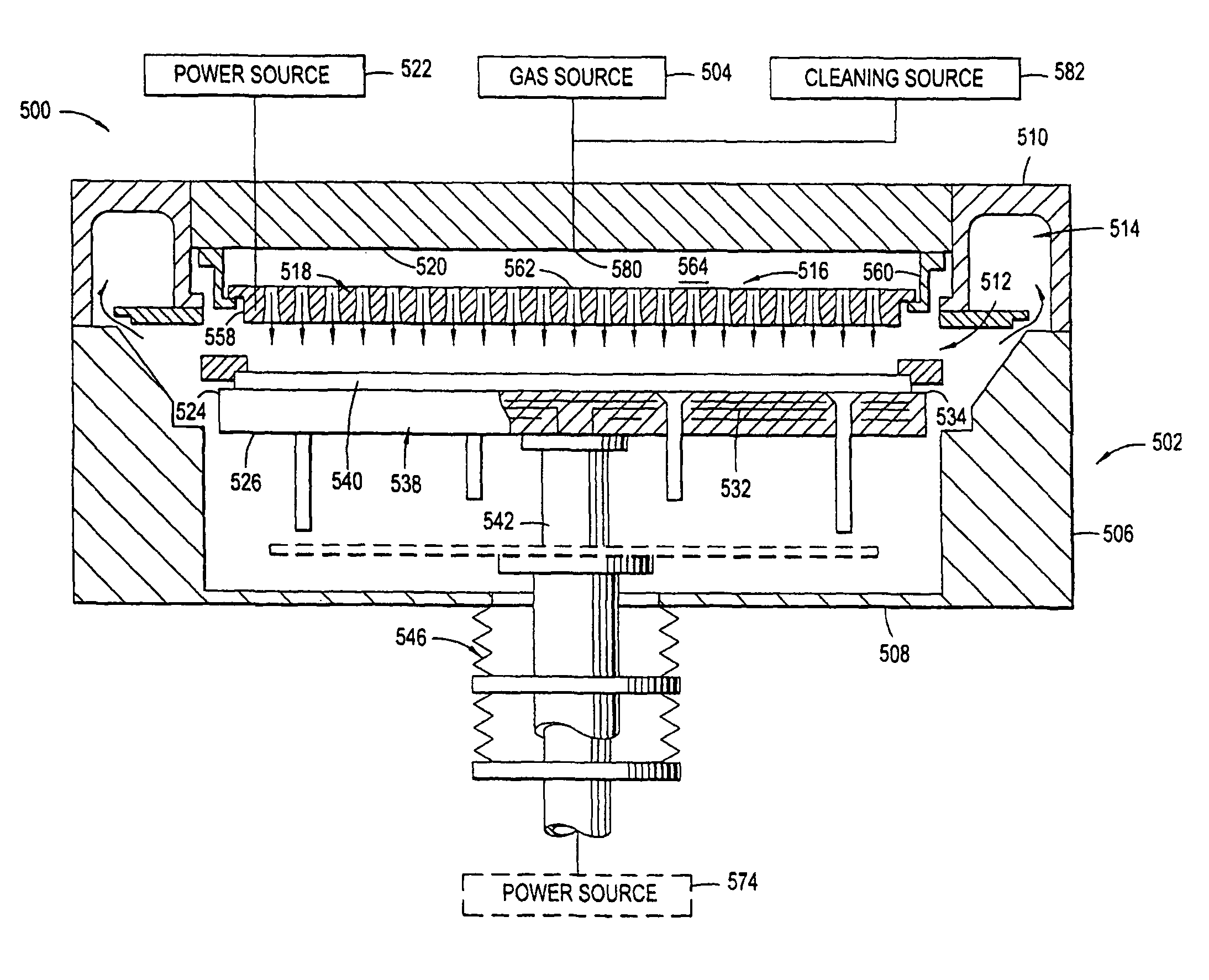
[0044]The invention generally provides a gas distribution assembly for providing gas delivery within a processing chamber. The invention is illustratively described below in reference to a plasma enhanced chemical vapor deposition system configured to process large area substrates, such as a plasma enhanced chemical vapor deposition (PECVD) system, available from AKT, a division of Applied Materials, Inc., Santa Clara, Calif. However, it should be understood that the invention has utility in other system configurations such as etch systems, other chemical vapor deposition systems and any other system in which distributing gas within a process chamber is desired, including those systems configured to process round substrates.

[0045]For SiN films, the center thick uniformity problem has been solved by varying the size and / or distribution of cathode cavities on the downstream surface of a PECVD gas diffuser plate. The cathode cavities enhance plasma ionization in the PECVD chamber. Beca...


PUM

PropertyMeasurementUnit
diameteraaaaaaaaaa
diameteraaaaaaaaaa
flaring angleaaaaaaaaaa

Abstract

Embodiments of a gas distribution plate for distributing gas in a processing chamber are provided. In one embodiment, a gas distribution assembly for a plasma processing chamber comprises a diffuser plate with gas passages passing between its upstream and downstream sides and hollow cathode cavities at the downstream side of the gas passages. The downstream side of the diffuser plate has a curvature to improve the thickness uniformity and film property uniformity of thin films deposited by PECVD, particularly SiN and amorphous silicon films. The curvature is preferably described by an arc of a circle or ellipse, the apex thereof located at the center point of the diffuser plate. In one aspect, the hollow cathode cavity volume density, surface area density, or the cavity density of the diffuser increases from the center of the diffuser to the outer edge. Methods for manufacturing such a diffuser plate are also provided.

Description

[0001]This application claims benefit to U.S. provisional patent application Ser. No. 60 / 587,173, filed Jul. 12, 2004. The disclosure of the aforementioned related patent application is herein incorporated by reference in its entirety to the extent not inconsistent with the claimed invention.[0002]This application is a continuation-in-part of U.S. patent application Ser. No. 11 / 021,416, filed Dec. 22, 2004 now U.S. Pat. No. 7,785,672. This application is a continuation-in-part of U.S. patent application Ser. No. 11 / 143,506, filed Jun. 2, 2005 now abandoned. This application is a continuation-in-part of U.S. patent application Ser. No. 10 / 962,936, filed Oct. 12, 2004 now abandoned. This application is a continuation-in-part of U.S. patent application Ser. No. 10 / 889,683, filed Jul. 12, 2004, which claims benefit of U.S. provisional patent application Ser. No. 60 / 570,876, filed May 12, 2004. The disclosure of each of the aforementioned related patent applications is herein incorporate...

Claims


Application Information

Patent Timeline
Patent Type & Authority Patents(United States)
IPC IPC(8): C23C16/455C23F1/00H01L21/306C23C16/06C23C16/22
CPCH01J37/3244H01J37/32449
Inventor CHOI, SOO YOUNGPARK, BEOM SOOWHITE, JOHN M.TINER, ROBIN L.
Owner APPLIED MATERIALS INC
Why Eureka
Try Eureka