Axially-movable rotary switch

a rotary switch and axial motion technology, applied in the direction of contact driving mechanism, contact mechanism, electrical apparatus, etc., can solve the problems of large occurring friction of conventional switches, unreliable switch action, elastic piece and electrode wear after a long period of use, etc., and achieve the effect of convenient operation

Inactive Publication Date: 2011-12-13
SOLTEAM ELECTRONICS
View PDF5 Cites 15 Cited by
  • Summary
  • Abstract
  • Description
  • Claims
  • Application Information

AI Technical Summary

Benefits of technology

[0008]The object of the present invention is to provide an axially-movable rotary switch, whereby a user can switch the states between a closed circuit and an open circuit by axially drawing / pressing the knob. Thus, the operation is easy with a good feeling. Furthermore, the frictional interference will not be generated.
[0010]The present invention has advantageous features as follows. Since the elastic piece of the switching rod is provided to correspond to the electrical contacts of the substrate, the user can switch the states between a closed circuit and an open circuit by axially drawing the knob relatively to the hollow casing. Thus, the operation is easy with a better feeling. Furthermore, when switching the states between a closed circuit and an open circuit, the contact between the elastic piece and the electrical contacts will not generate unnecessary frictional interference, so that the lifetime of the device can be extended.

Problems solved by technology

However, the conventional switch has the drawback of large occurring friction.
Since the switch of an electronic device may have to generate switching actions very frequently, the elastic piece and electrodes may become worn down from friction after a long period of usage.
As a result, the switch action may become unreliable.
Furthermore, a worn down switch cannot provide the user with a good operational feeling.

Method used


Image

  • Axially-movable rotary switch
  • Axially-movable rotary switch
  • Axially-movable rotary switch

Examples


Embodiment Construction

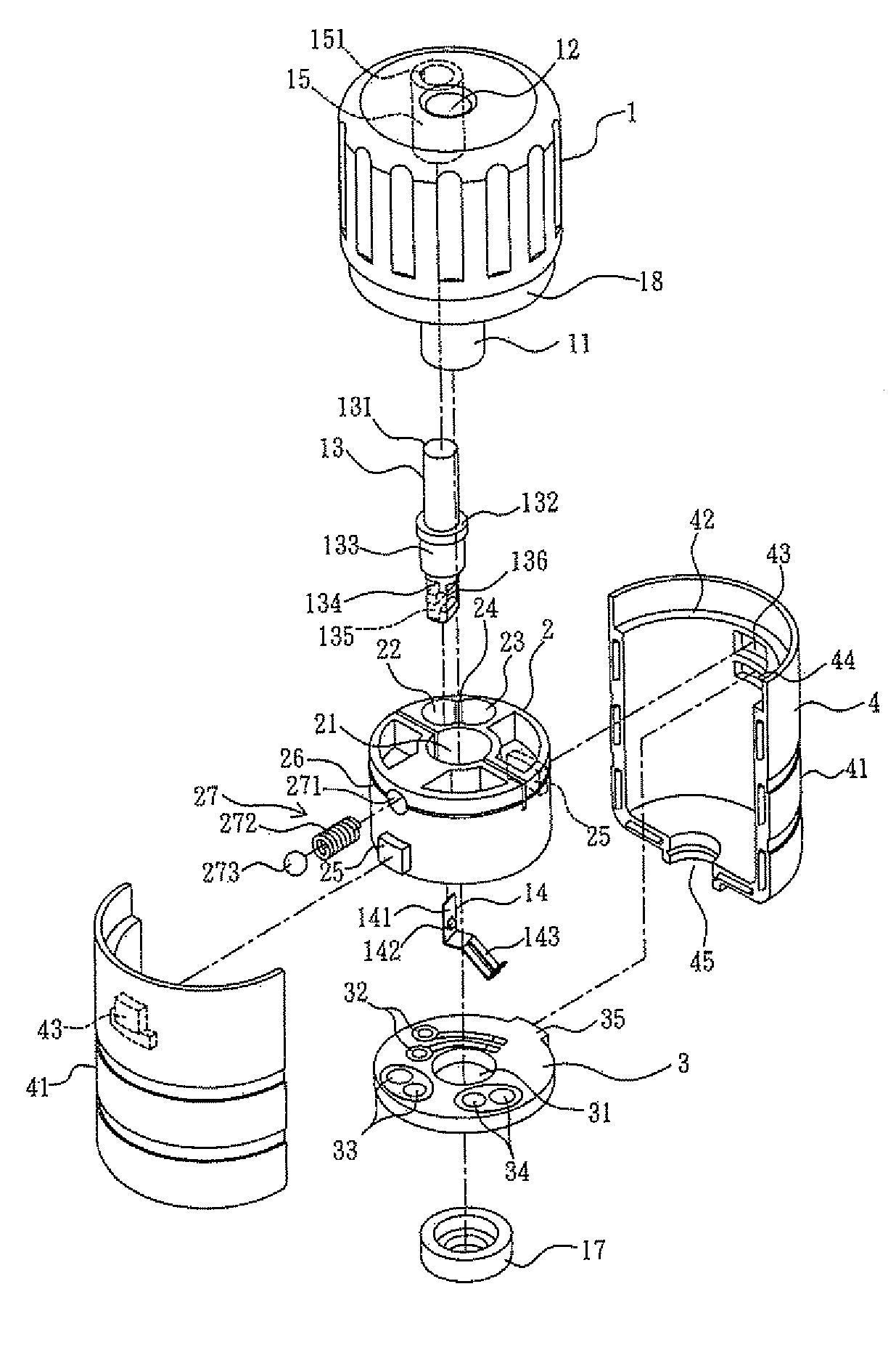
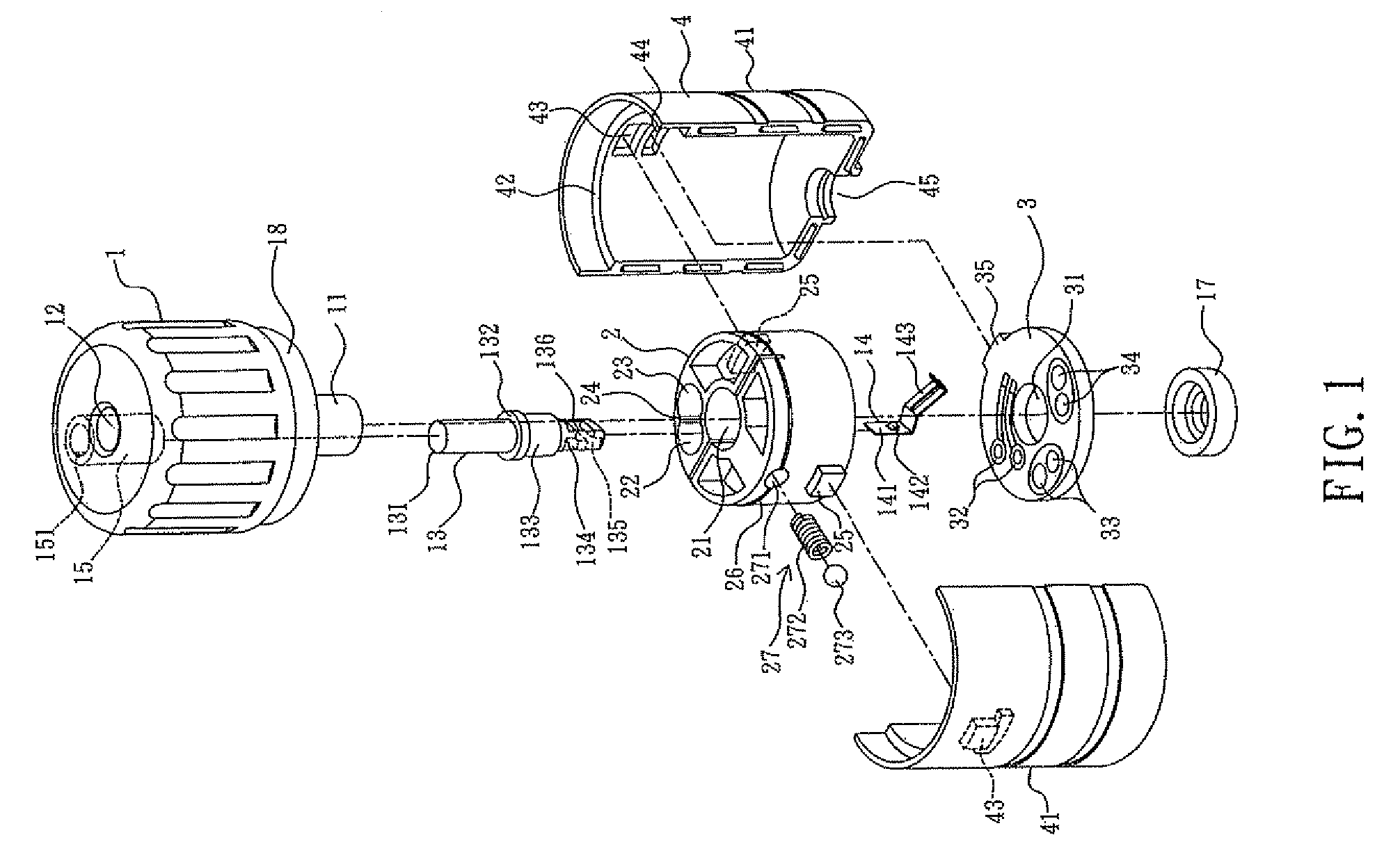
[0020]Please refer to FIGS. 1 to 8. The present invention provides an axially-movable rotary switch, which includes a knob 1, a fixing base 2, a substrate 3 and a hollow casing 4.

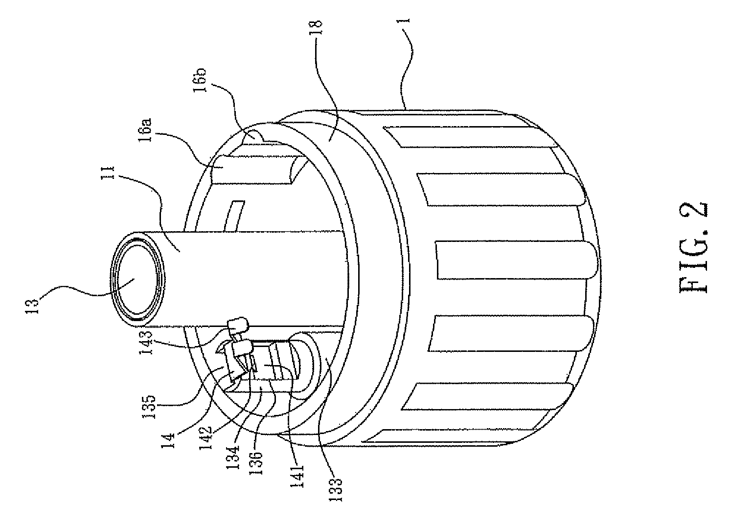
[0021]As shown in FIGS. 1 and 2, the knob 1 comprises a shaft 11, a shaft hole 12, a switching rod 13, an elastic piece 14, a connecting pipe 15, two locking grooves 16a, 16b, a end piece 17 and a stepped ring 18.

[0022]The knob 1 is a cylindrical body with an open end. The shaft 11 extends downwards from the center of the top wall of the knob 1 to the outside. The shaft hole 12 is a circular hole which passes through the shaft 11 and the shaft hole 12 penetrates through the top wall of the knob 1. A conductive line (not shown) can penetrate the shaft hole 12 to be electrically connected to electrical contacts of the substrate 3. The end piece 17 is an annular body which is fixed to the distal end of the shaft 11 for abutting the lower end surface of the fixing base 2. The stepped ring 18 is surrounding the ...


PUM


Abstract

An axially-movable rotary switch includes a casing, a fixing base, a substrate and a knob. The fixing base is fixed in the hollow casing. The substrate is fixed below the fixing base. The knob is pivotally disposed on the upper end of the hollow casing. The switching rod of the knob eccentrically penetrates a positioning hole of the fixing base. The elastic piece is disposed at the distal end of the switching rod and is brought into contact with the electrical contacts of the substrate. With the elastic piece of the switching rod being arranged to correspond to the electrical contacts of the substrate, a user can switch the states between a closed circuit and an open circuit by axially drawing / pressing the knob. Further, the contact between the elastic piece and the electrical contacts will not generate unnecessary frictional interference, so that the lifetime of the device can be extended.

Description

CROSS-REFERENCE TO RELATED APPLICATION[0001]This application claims priority under 35 U.S.C. §119 to Taiwan Patent Application No. 097222612, filed on Dec. 17, 2008, in the Taiwan Intellectual Property Office, the entire contents of which are hereby incorporated by reference.BACKGROUND OF THE INVENTION[0002]1. Field of the Invention[0003]The present invention relates to an axially-movable rotary switch, and in particular to an axially-movable rotary switch in which a closed circuit and an open circuit can be switched.[0004]2. Description of Related Art[0005]The state of an electronic device is usually changed by means of a switch. The most common switch is a two-stage switch for changing between a closed circuit and an open circuit. This kind of switch is operated by means of pressing or pushing. The press switch engages with an elastic piece, so that the elastic force of the elastic piece is used to switch states between a closed circuit and an open circuit. In the push switch, two...

Claims


Application Information

Patent Timeline
Patent Type & Authority Patents(United States)
IPC IPC(8): H01H13/62H01H19/14
CPCH01H3/20H01H19/11H01H19/36H01H19/56
Inventor HUANG, CHEN-HONGYEH, TA-FENG
Owner SOLTEAM ELECTRONICS
Why Eureka
Try Eureka