Perpendicular magnetic recording head having a recessed magnetic base layer

a magnetic base layer and recording head technology, applied in the direction of metal sheet core heads, data recording, instruments, etc., can solve the problem that the conventional pmr head b>10/b> may have poor write efficiency at hither densities

Active Publication Date: 2011-12-13
WESTERN DIGITAL TECH INC
View PDF19 Cites 155 Cited by
  • Summary
  • Abstract
  • Description
  • Claims
  • Application Information

AI Technical Summary

Benefits of technology

[0007]FIG. 1 depicts a co

Problems solved by technology

Although the conventional PMR head 10 functions, there may be drawbacks, particularly in adapting the conventional PMR he

Method used


Image

  • Perpendicular magnetic recording head having a recessed magnetic base layer
  • Perpendicular magnetic recording head having a recessed magnetic base layer
  • Perpendicular magnetic recording head having a recessed magnetic base layer

Examples


Embodiment Construction

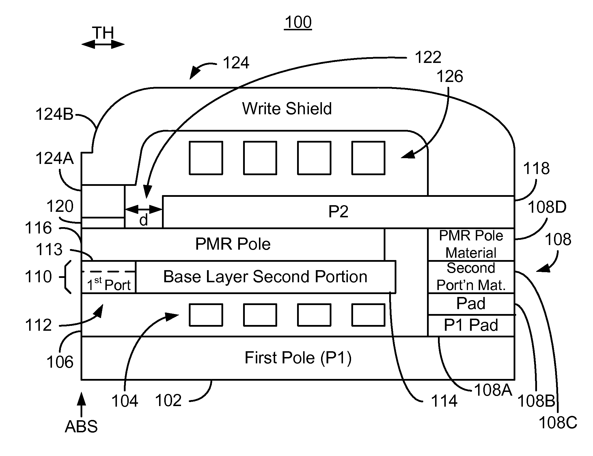
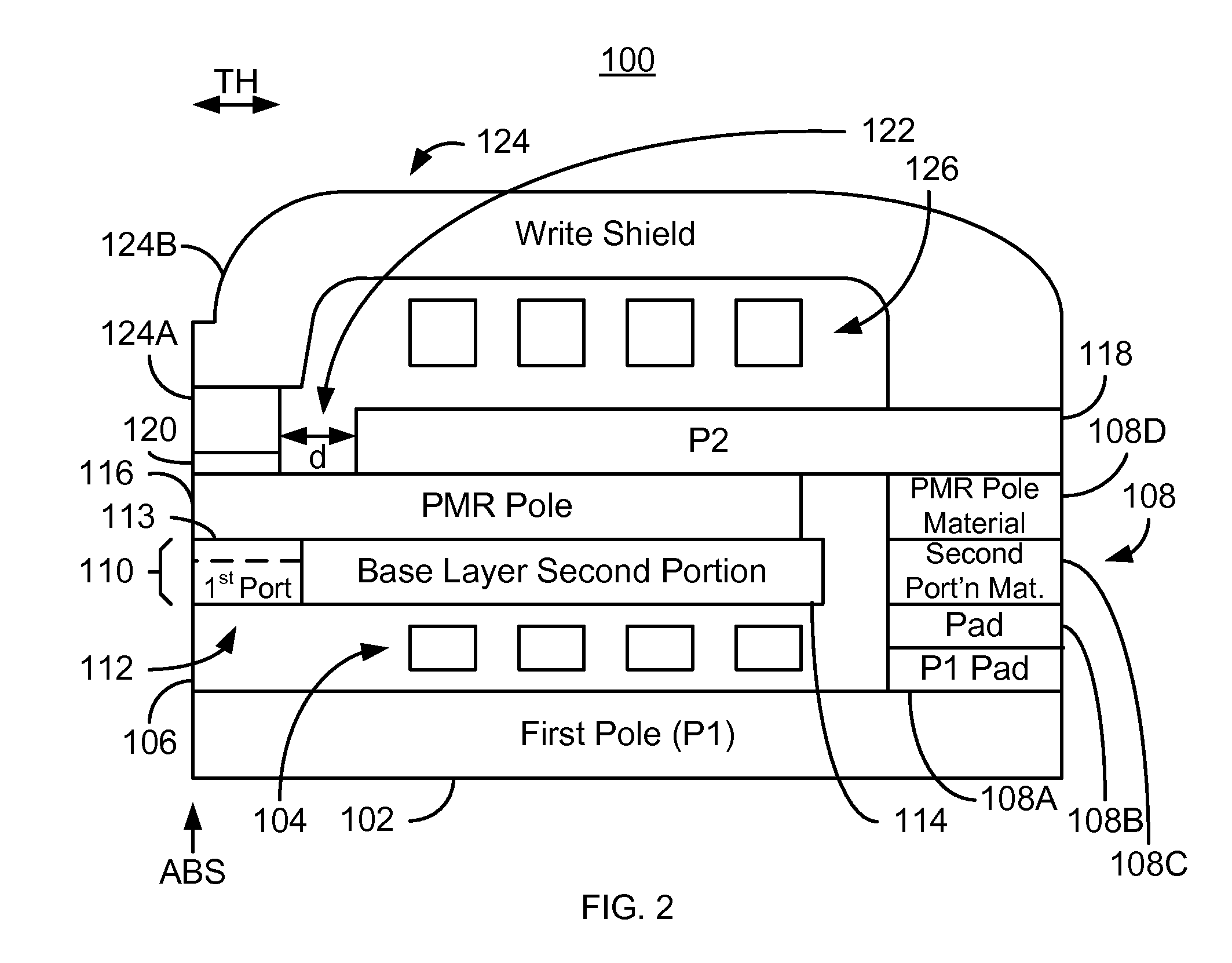
[0013]FIG. 2 is a diagram depicting an exemplary embodiment of a PMR transducer 100. The PMR transducer 100 includes at least a first pole (P1) 102, a first coil 104, an insulator 106, optional pads 108, a base layer 110, a PMR pole 116, a second pole (P2) 118, a write gap 120, an insulator 122, a write shield 124, and a second coil 126. For clarity, the PMR transducer 100 is not drawn to scale. Although shown alone, the PMR transducer 100 may be part of a head that includes a slider and may also include a read transducer (not shown).

[0014]The P1102 and PMR pole 116 are ferromagnetic and, therefore, may include materials such as Fe, Ni, and Co. The pad 108 may include structure formed at different times. For example, the pad 108 may include a P1 pad 108A, an additional pad 108B connecting the P1 pad to a portion 108C of the pad formed with the second portion 114 of the base layer 110, the portion 108C of the pad 108 formed with the second portion 114 of the base layer 110, and a por...


PUM


Abstract

A method and system for providing a magnetic transducer having an air-bearing surface (ABS) are described. The magnetic transducer includes a base layer, a perpendicular magnetic recording (PMR) pole on the base layer, an additional pole, a write shield, a write gap between the PMR pole and a portion of the write shield, and coil(s) that energize at least the additional pole. The base layer includes a first portion proximate to the ABS and a second portion recessed from the ABS. The first portion is nonmagnetic, while the second portion is magnetic. The PMR pole has a first front portion proximate to the ABS. The additional pole has a second front portion recessed from the ABS. At least a portion of the additional pole resides between the PMR pole and write shield. At least a portion of the write gap resides on the front portion of the PMR pole.

Description

BACKGROUND[0001]In order to write data to and read data from a media, a recording head is typically used. FIG. 1 depicts a conventional perpendicular magnetic recording (PMR) head 10 that includes a read transducer 12 and a conventional write transducer 14. For clarity, FIG. 1 is not drawn to scale. Although both the conventional read transducer 12 and the conventional write transducer 14 are shown, the conventional write transducer 14 may be part of a head that only performs writing. In addition, the conventional PMR head 10 may also include a slider (not shown).[0002]The read transducer 12 includes a first shield (S1) 15, a read sensor 16, and a second shield (S2) 18. The conventional PMR write transducer 14 includes a first pole 20 that may be separate from the S218, a first coil 22, a conventional PMR pole 24, a second pole (P2) 26, an insulating space 28, a write gap 30, a conventional write shield 32 that may include portions 32A and 32B, and a second coil 34. The conventional...

Claims


Application Information

Patent Timeline
IPC IPC(8): G11B5/147
CPCG11B5/1278G11B5/3116
Inventor SHEN, YONGZHANG, LEI LARRYCHEN, YINGJIANTRAN, UT
Owner WESTERN DIGITAL TECH INC
Why Eureka
Try Eureka