

Vehicle steering device
a steering device and vehicle technology, applied in the direction of mechanical control devices, pedestrian/occupant safety arrangements, instruments, etc., can solve the problems of inability to reliably support the rear surface, inability of the airbag to reliably secure the driver restraint performance, and the handle is of a non-circular shape, so as to reduce the possibility of interference (collision) and reduce the possibility of interferen
- Summary
- Abstract
- Description
- Claims
- Application Information
AI Technical Summary
Benefits of technology
Problems solved by technology
Method used
Image

Examples
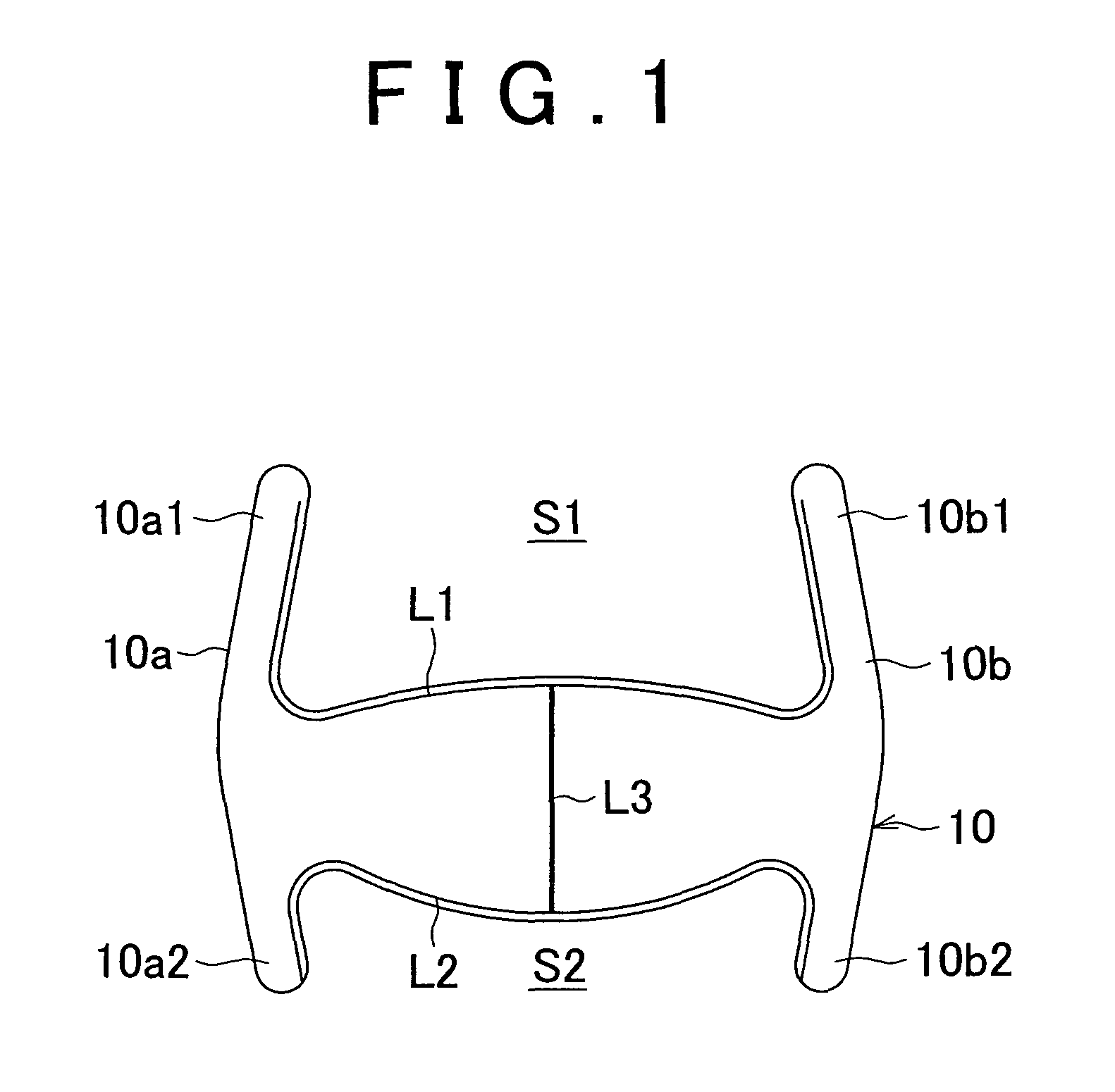
first embodiment
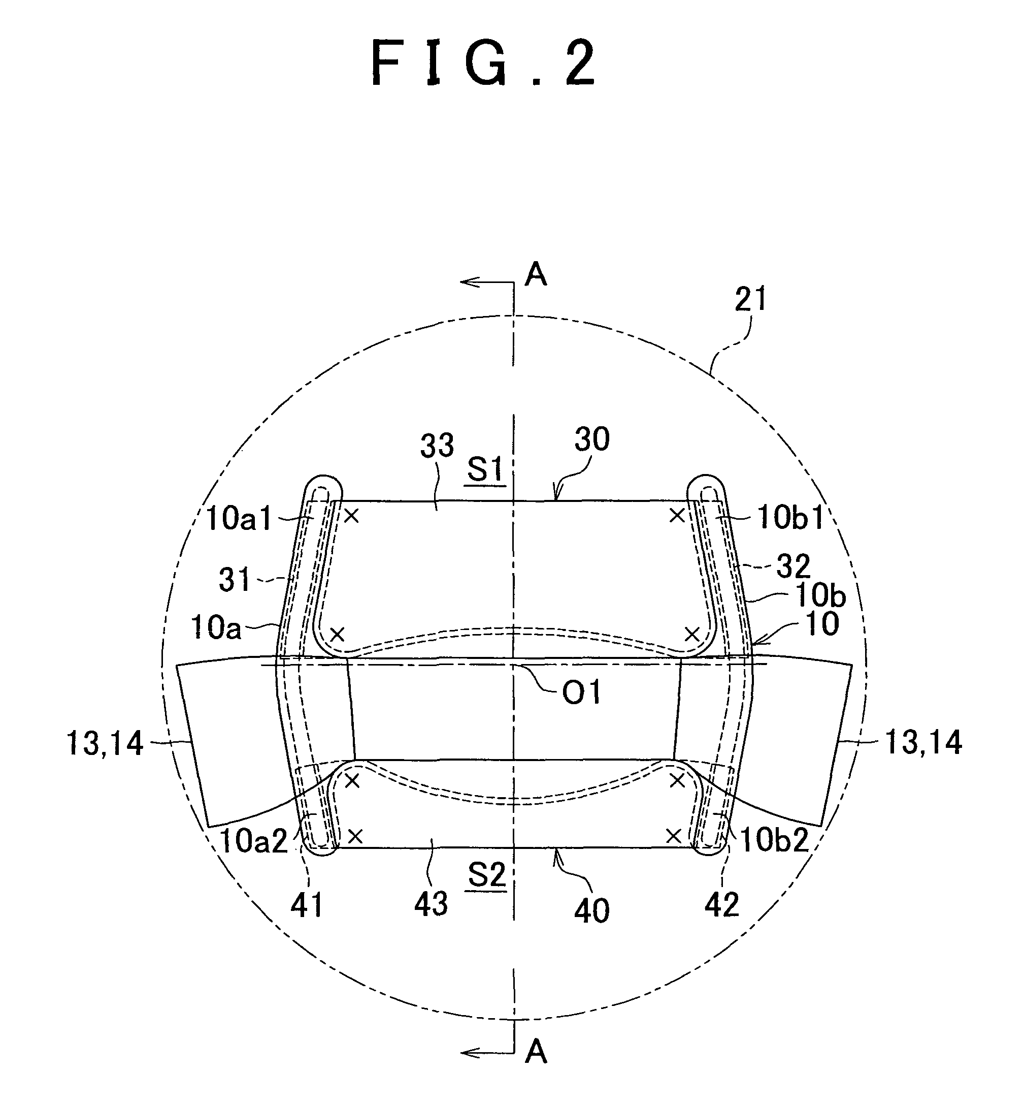
In the first embodiment, an upper support mechanism 30 and a lower support mechanism 40 are provided in the steering handle 10. The upper support mechanism 30 is provided in a corresponding relationship with the upper non-grip space S1 and is movable upwardly. The lower support mechanism 40 is provided in a corresponding relationship with the lower non-grip space S2 and is movable downwardly. The upward displacement amount of the upper support mechanism 30 is set greater than the downward displacement amount of the lower support mechanism 40.
Referring to FIGS. 2 through 5, each of the support mechanisms 30 and 40 includes a pair of left and right fabric sleeves 31 and 32 or 41 and 42 capable of retracting and extending along the main core member 11 of the steering handle 10 and a rectangular tension fabric 33 or 43 sewn at its short-side ends to the flank portions of the fabric sleeves 31 and 32 or 41 and 42, the tension fabric 33 or 43 being capable of retracting and extending toge...
second embodiment
In the second embodiment, an upper support mechanism 130 and a lower support mechanism 140 are provided in the steering handle 110. The upper support mechanism 130 is provided in a corresponding relationship with the upper non-grip space S11 and is movable upwardly. The lower support mechanism 140 is provided in a corresponding relationship with the lower non-grip space S12 and is movable downwardly. The upward displacement amount of the upper support mechanism 130 is set greater than the downward displacement amount of the lower support mechanism 140.
Referring to FIGS. 6 and 7, each of the support mechanisms 130 and 140 includes a pair of left and right reaction force supporting arms 131 and 132 or 141 and 142 and a tension cloth (tension member) 133 or 143 fixed at its lateral end portions to the distal end portions of the reaction force supporting arms 131 and 132 or 141 and 142, the tension cloth 133 or 143 being adapted to be taughtly stretched in the non-grip space S11 or S12....
third embodiment
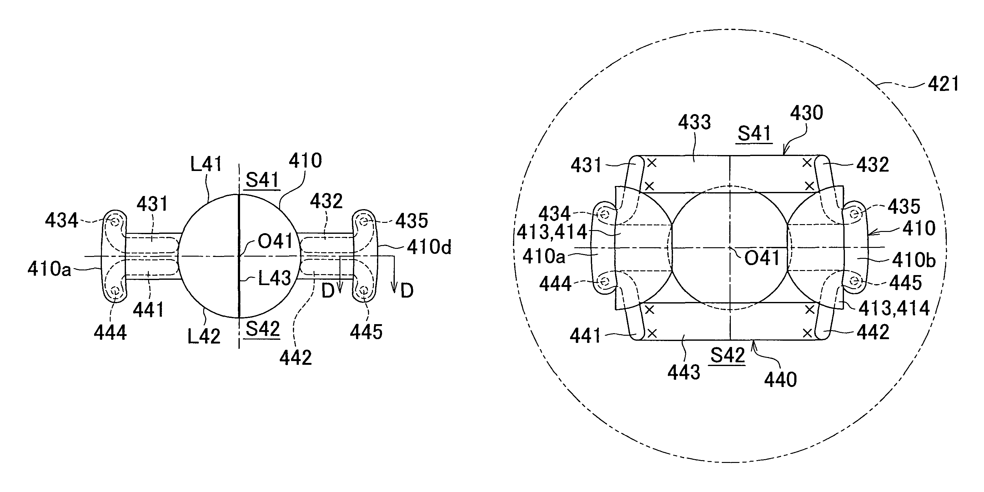
In the third embodiment, an upper support mechanism 230 and a lower support mechanism 240 are provided in the steering handle 210. The upper support mechanism 230 is provided in a corresponding relationship with the upper non-grip space S21 and is movable upwardly. The lower support mechanism 240 is provided in a corresponding relationship with the lower non-grip space S22 and is movable downwardly. The upward displacement amount of the upper support mechanism 230 is set greater than the downward displacement amount of the lower support mechanism 240.
Referring to FIGS. 9 and 10, each of the support mechanisms 230 and 240 includes a pair of left and right reaction force supporting arms 231 and 232 or 241 and 242 fitted into the hollow core members 211 of the steering handle 210 and linking strings 233 and 234 or 243 and 244 connected to the base ends of the reaction force supporting arms 231 and 232 or 241 and 242 and also to the pertinent portions of the airbag 221.
The upper reactio...
PUM
 Abstract
Description
Claims
Application Information