
Roofing tile system

a technology of roofing tiles and roofing panels, applied in the field of roofing tiles, can solve the problems of flexible roofing tiles being known to tear from the secured section or break free in sheets, rigid roofing systems are generally substantially more expensive than flexible roofing systems, and are expected to have a significantly longer useful li

Inactive Publication Date: 2011-12-27
WORLEY RONALD J +1
View PDF21 Cites 8 Cited by
  • Summary
  • Abstract
  • Description
  • Claims
  • Application Information

AI Technical Summary

Benefits of technology

[0012]It is yet another object of the present invention to provide a roofing tile system of interlocked rows of tiles in side-by-side relation, which is secure in a high wind.

Problems solved by technology

A moderate wind may cause movement of the exposed ends of flexible roofing tiles.
Flexible tiles are known to tear from the secured section or break free in sheets when exposed to a strong enough wind.
The rigid roofing systems are generally substantially more costly than flexible roofing systems and are expected to have a significantly longer useful life.
The nails may become dislodged causing tiles to slide or become free from their position exposing the roof to possible leaks and tile breakage.

Method used


Image

  • Roofing tile system
  • Roofing tile system
  • Roofing tile system

Examples


Embodiment Construction

[0028]Detailed embodiments of the present invention are disclosed herein. It will be understood that the disclosed embodiments are merely exemplary of the invention that may be embodied in various and alternative forms. The figures are not necessarily to scale, and some features may be exaggerated or minimized to show details of particular embodiments, features, or elements. Specific structural and functional details, dimensions, or shapes disclosed herein are not limiting but serve as a basis for the claims and for teaching a person of ordinary skill in the art the described and claimed features of embodiments of the present invention.

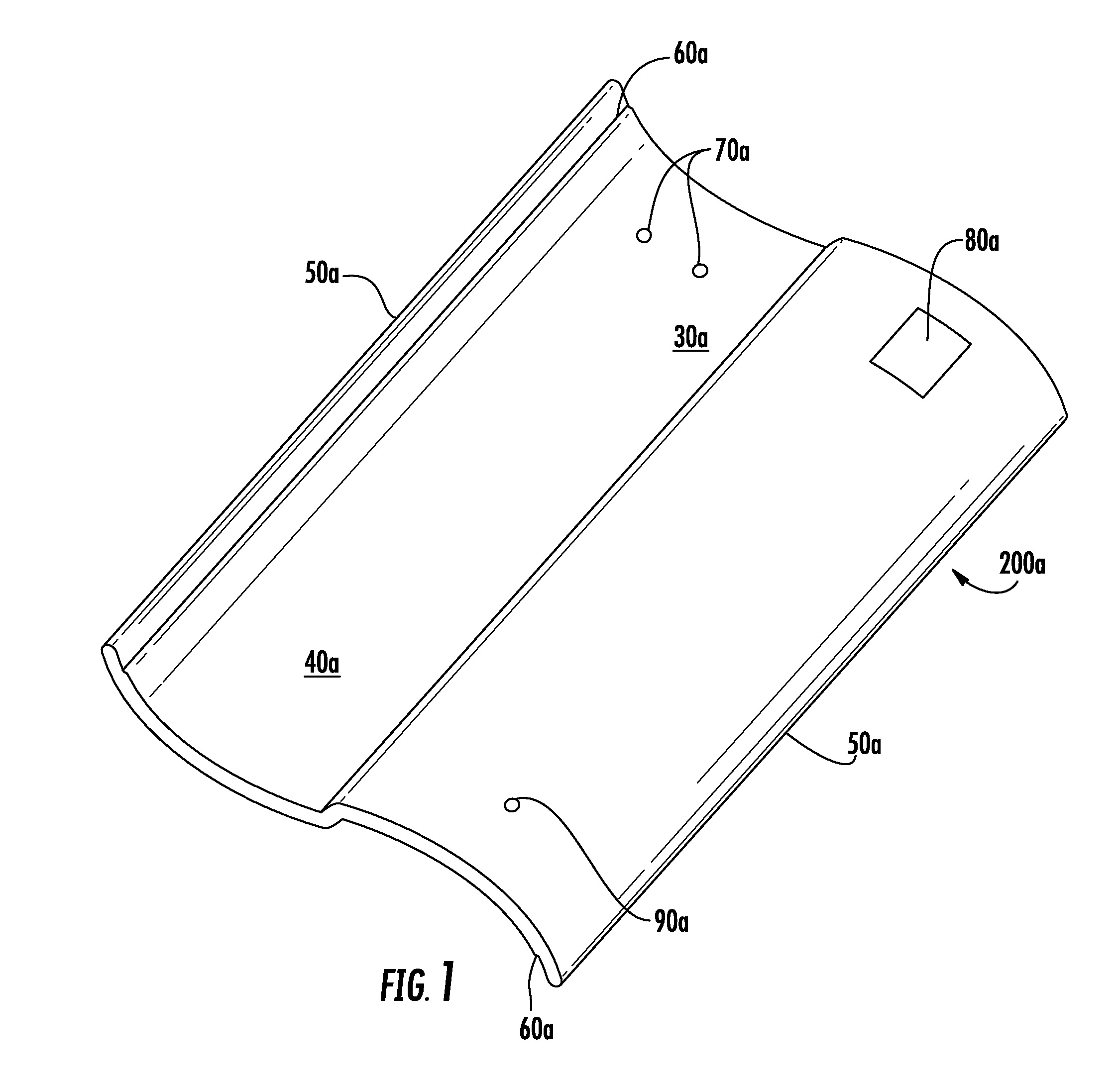
[0029]For purposes of description herein, the terms “upper”, “lower”, “left”, “rear”, “right”, “front”, “vertical”, “horizontal”, and derivatives thereof shall relate to the invention as oriented in FIG. 1. However, one will understand that the invention may assume various alternative orientations and step sequences, except where expressly specified t...


PUM


Abstract

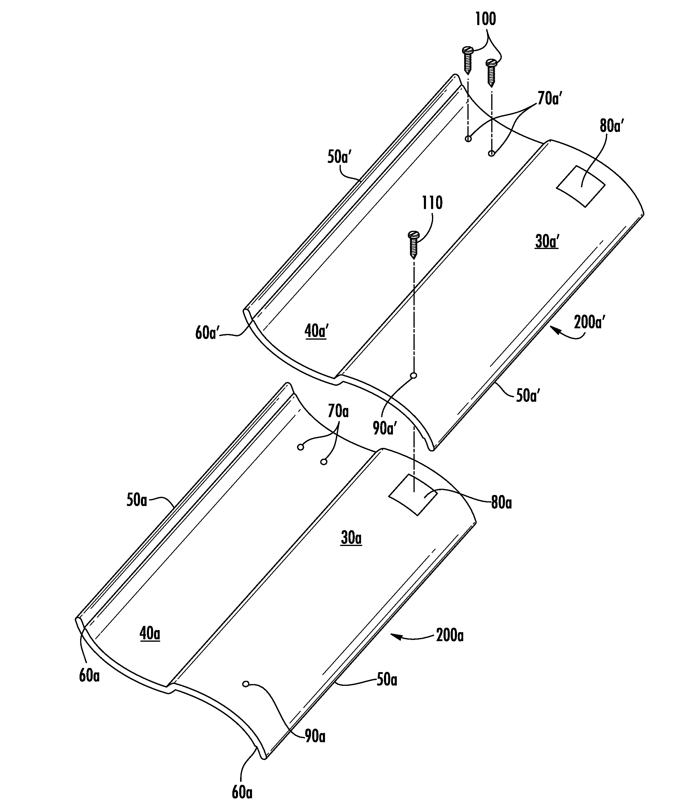
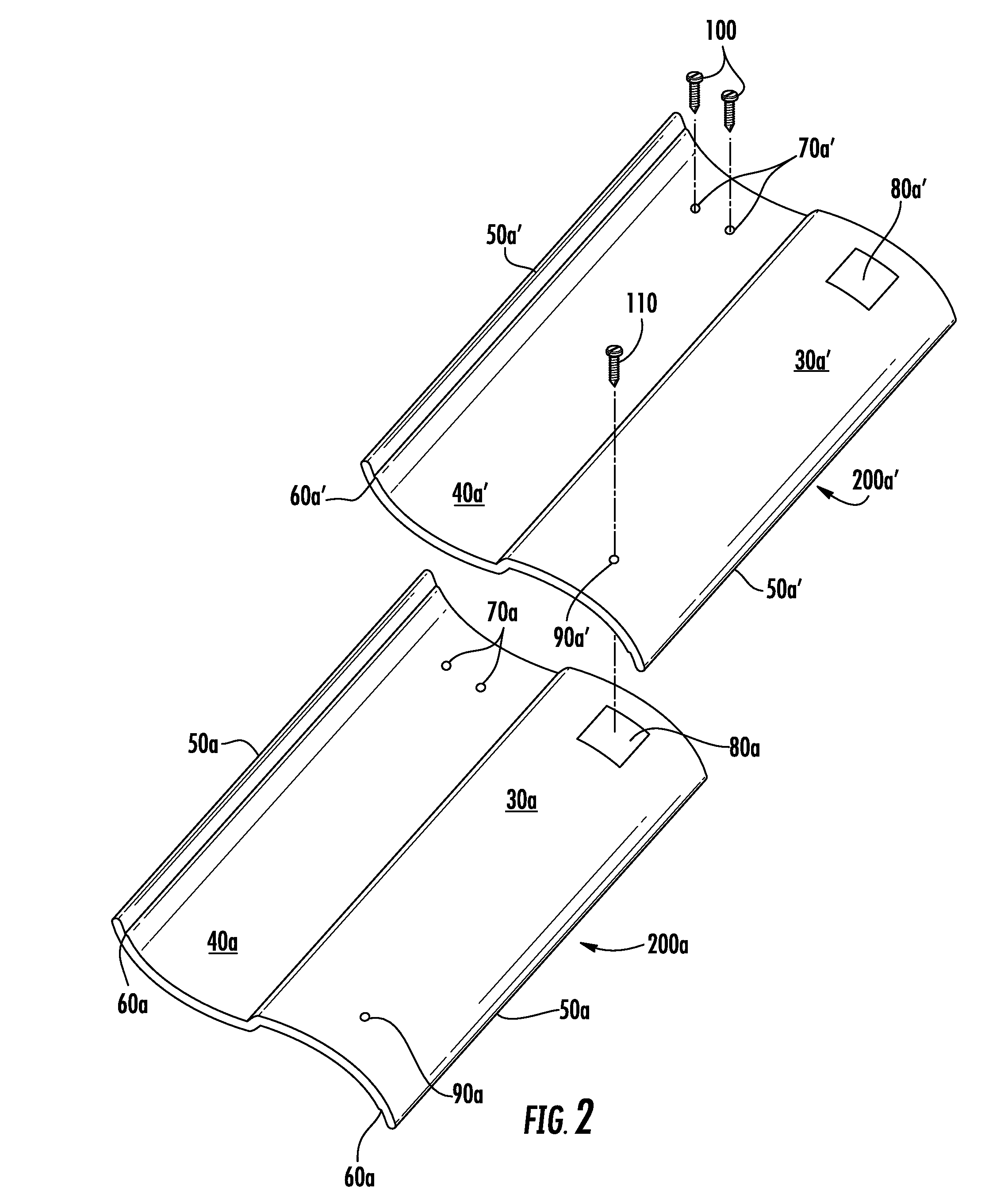
A roofing tile system provides a secure covering for a building roof and comprises a plurality of rigid tiles attached on a pitched roofing substrate in multiple interlocked rows of tiles. Each tile includes a protected end partially overlapped by another tile in an adjacent row, and an exposed end. The protected end of each tile includes at least one attachment hole and at least one anchoring panel. The exposed end of each tile includes at least one interlock hole. Primary roofing screws are provided for driving through attachment holes and into the substrate for attaching tiles in side-by-side relation to form multiple rows. Secondary roofing screws are provided for driving through interlock holes and into the interlock panel of a partially overlapped tile in an adjacent row, for interlocking the exposed ends of the roofing tiles with anchoring panels in adjacent tiles.

Description

BACKGROUND OF THE INVENTION[0001]1. Field of the Invention[0002]The invention generally relates to roofing tiles and more particularly to a system including a plurality of partially overlapping rows of roofing tiles in side-by-side relation on a pitched roof, with neighboring roofing tiles in adjacent rows interlocked.[0003]2. Description of the Prior Art[0004]A building roof typically includes a layer of rigid material attached to joists or beams to form planar substrates. The roof is made weather tight by the application, on the substrates, of weather proof material having provisions for positive drainage. A typical arrangement is a pitched roof consisting of one or more sections of planar substrates, pitched at an angle to promote downward run-off from an uppermost edge toward a lowermost edge. Uppermost edges of adjacent sections may meet at a peak defined by the boundary between the sections. Each roof section is typically covered by weather proof tiles attached in overlapping ...

Claims


Application Information

Patent Timeline
Patent Type & Authority Patents(United States)
IPC IPC(8): E04D1/00
CPCE04D1/34E04D2001/3423E04D2001/3438E04D2001/3447E04D2001/3467E04D2001/3485E04D1/2918E04D1/29
Inventor WORLEY, RONALD J.ROBINSON, HARRY
Owner WORLEY RONALD J
Learn More