Hot melt ink delivery reservoir pump subassembly

Active Publication Date: 2011-12-27
XEROX CORP
View PDF4 Cites 0 Cited by
  • Summary
  • Abstract
  • Description
  • Claims
  • Application Information

AI Technical Summary

Problems solved by technology

The introduction of the pressurized air pulses can cause foaming, overfill, and print head leakage or ‘drooling’ if more than 2 colors are simultaneously delivered to a single head.
Further, this implementation has limitations as to the maximum flow rate of the ink and the number of colors that can be delivered to the print heads simultaneously.

Method used


Image

  • Hot melt ink delivery reservoir pump subassembly
  • Hot melt ink delivery reservoir pump subassembly
  • Hot melt ink delivery reservoir pump subassembly

Examples


Embodiment Construction

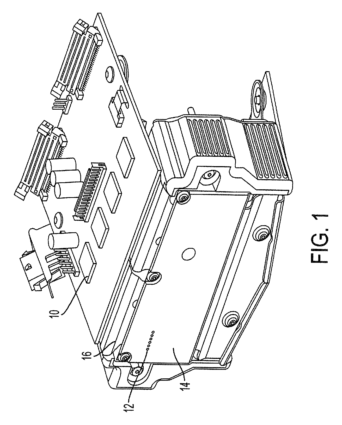
FIG. 1 shows an example of an ink jet print head. The print head has an ink reservoir 10 that receives ink from an ink source, not shown. In the case of a hot melt ink jet printer, the ink source generally consists of solid ink sticks melted by a heat source of some kind and then pumped to the ink reservoir such as 10. In typical ink jet printers, pressurized air provides the impetus to move the ink from the melting reservoir to the print head ink reservoir 10. For that reason, the print head ink reservoir may also be referred to as a high-pressure reservoir.

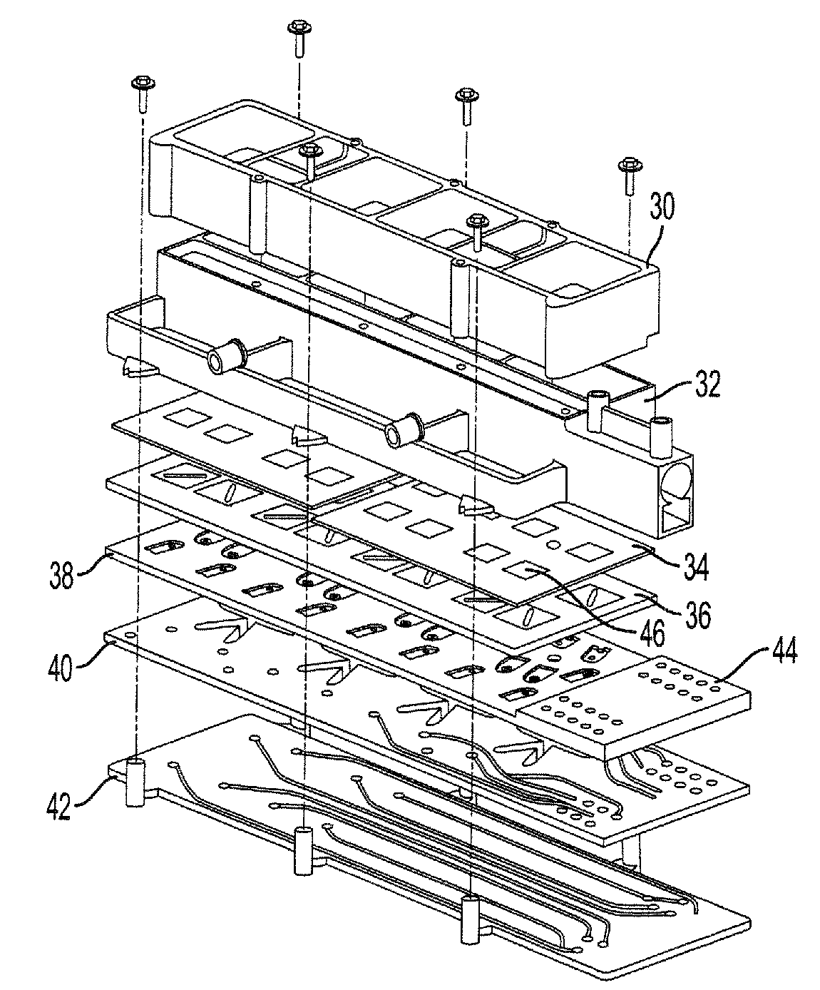
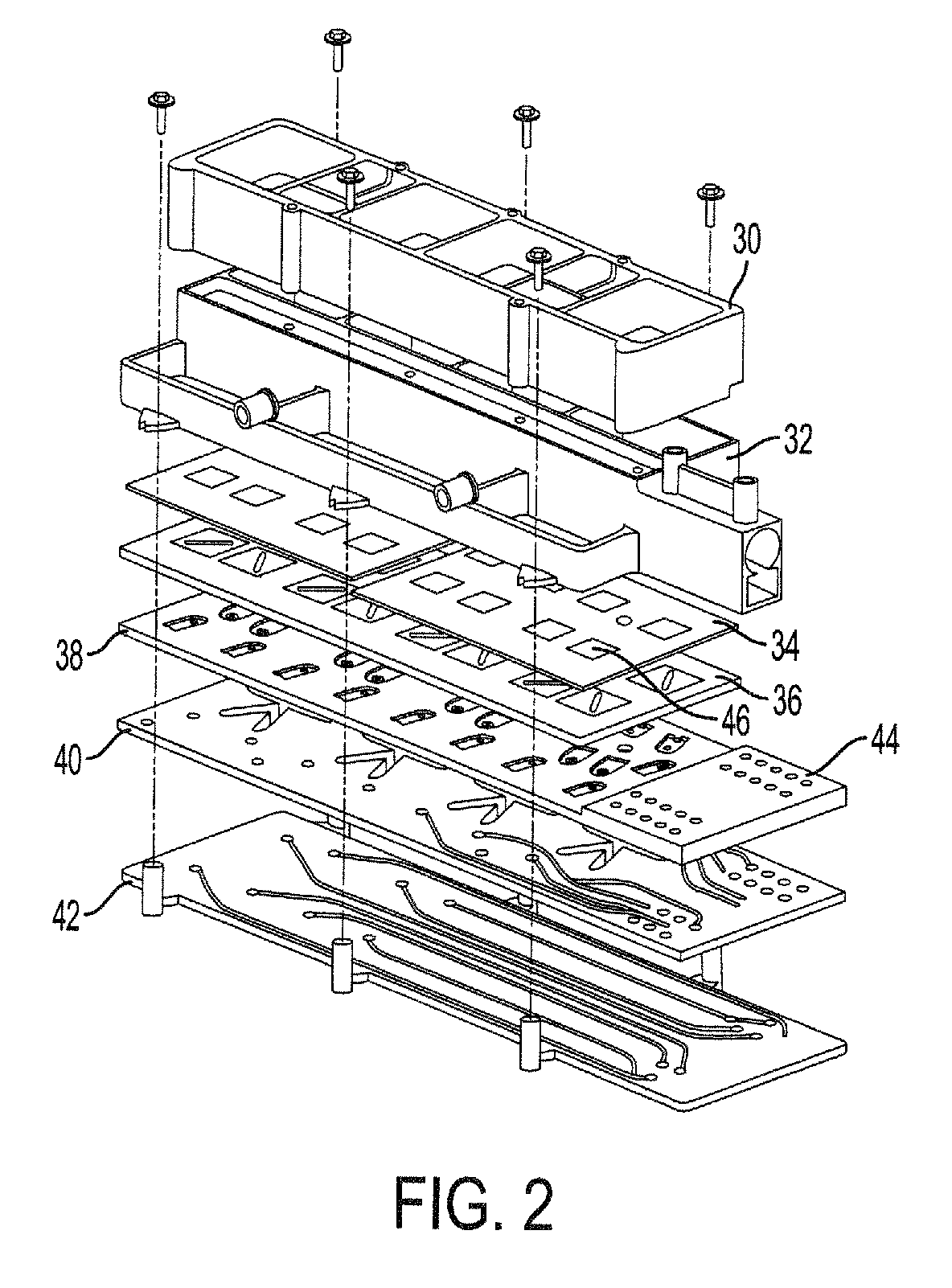
The print head ink reservoir may actually consist of several ink reservoirs, one for each color standard to the color printing process, cyan, yellow, magenta and black. The ink travels from the reservoirs through a series of outlet plates and manifold plates that route the ink to an array of jets such as 12 on an aperture plate or jet stack 14. A control circuit 16 controls the exit of the ink through the jet stack to form drops...


PUM


Abstract

A print head pump assembly has a piezo element plate having an array of piezoelectric elements, a channel plate having an array of channel regions corresponding to the array of piezoelectric elements, and a valve plate having an array of reed valve pairs corresponding to the array of channel regions. A print head assembly has at least one ink reservoir, an upper routing plate to receive ink from the ink reservoir, a lower routing plate to direct ink out of the print head, and a pump assembly to draw ink from the upper routing plate and deliver ink to the lower routing plate using piezoelectric diaphragms. A method of delivering ink to a print substrate includes providing ink to a low-pressure reservoir of a print head, drawing ink out of the low-pressure reservoir through an upper routing plate using a pump assembly internal to the print head, and pumping ink out of the print head through a lower routing plate using the pump assembly, such that the drawing and pumping processes continuously alternate.

Description

BACKGROUNDInk delivery systems generally deliver ink from a reservoir to ports on a print head. The ink travels through umbilicals or tubing, enters the printhead and then ends up on a printing substrate as selected by the delivery system within the print head. In hot melt ink printers, the ink takes the form of solid ‘sticks’ of ink that is then melted into a first reservoir. Depending upon the configuration of the printer, the ink may travel from the first reservoir to a smaller reservoir closer to the print head until print demand requires delivery of the ink to the print head.Some current implementations of piezoelectric ink jet (PIJ) printers may use an ink delivery system to deliver ink to 16 ports on the print head asynchronously. These systems may contain 16 solenoid valves, air router manifolds, low and high pressure chambers, check valve disks, check ball assemblies and fluid routing plates. An air pulse drives the ink from the solenoid in a single plug flow, in some embod...

Claims


Application Information

Patent Timeline
IPC IPC(8): B41J2/045
CPCB41J2/14201B41J2/17593B41J2002/14362B41J2002/14419
Inventor LEIGHTON, ROGER G.DOMOTO, GERALD A.BITZ, BRIAN D.EDWARDS, KIRK S.
Owner XEROX CORP
Why Eureka
Try Eureka