Vertebral fixation device and tool for assembling the device

a technology of fixation device and tool, which is applied in the field of intervertebral fixation system, can solve the problems of slanting screw, not threading properly in the tulip, and reducing the service life of the device, so as to reduce the space occupied by the device and strengthen the system

Inactive Publication Date: 2011-12-27
TRAIBER
View PDF36 Cites 66 Cited by
  • Summary
  • Abstract
  • Description
  • Claims
  • Application Information

AI Technical Summary

Benefits of technology

The object of the invention consists of developing a first vertebral fixation device with optimised configuration that allow to adjust the various elements that make it up, particularly when it is being assembled on the bone, thereby ensuring that the elements are more firmly attached and that the system is stronger, while also aiming to minimise the space occupied by the device.

Problems solved by technology

One of the problems encountered in the use of these devices refers to the fact that because the vertebrae are very close together, it is very complicated to install the tulips on the same bar and they may even come into contact with each other.
Moreover, the installation of the set formed by the closing screw and the locking cap in the tulip is not exempt from a certain degree of complication, as there are no means to fix the position of the locking cap when the assembly commences with the screwing of the closing screw, and the locking cap prevents proper viewing of the cap-screw construct while it is being assembled in the tulip, leading to a situation where the screw may even be slanted and not thread properly in the tulip.
On the other hand, in some tulips, there is the problem that the threads on the closing screws do not thread fully onto the tulip, meaning that they could break or come loose when the device is installed on the vertebrae.

Method used


Image

  • Vertebral fixation device and tool for assembling the device
  • Vertebral fixation device and tool for assembling the device
  • Vertebral fixation device and tool for assembling the device

Examples


Embodiment Construction

The vertebral fixation device proposed in this invention is intended to provide a satisfactory solution to the aforementioned problems.

Two devices shall be described, one of which will be a vertebral fixation device to immobilise the vertebrates in all kinds of cases (deviations, depth, fractures . . . ) and another vertebral fixation device that we shall refer to as a lateral connector to correct more serious lateral deviations of the vertebrates.

First of all, the main vertebral fixation device will be described, followed by the tool used to assemble this fixation device and finally, the lateral connector will be described.

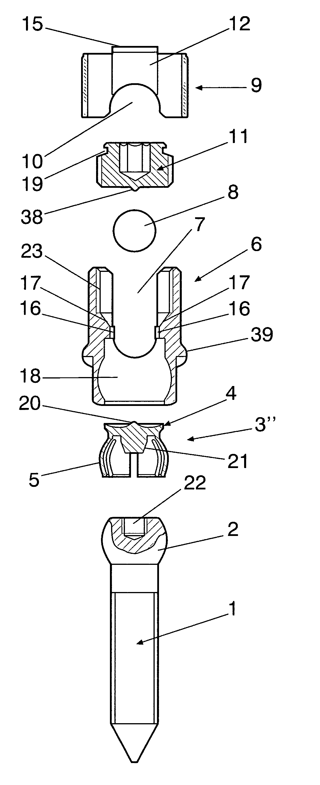
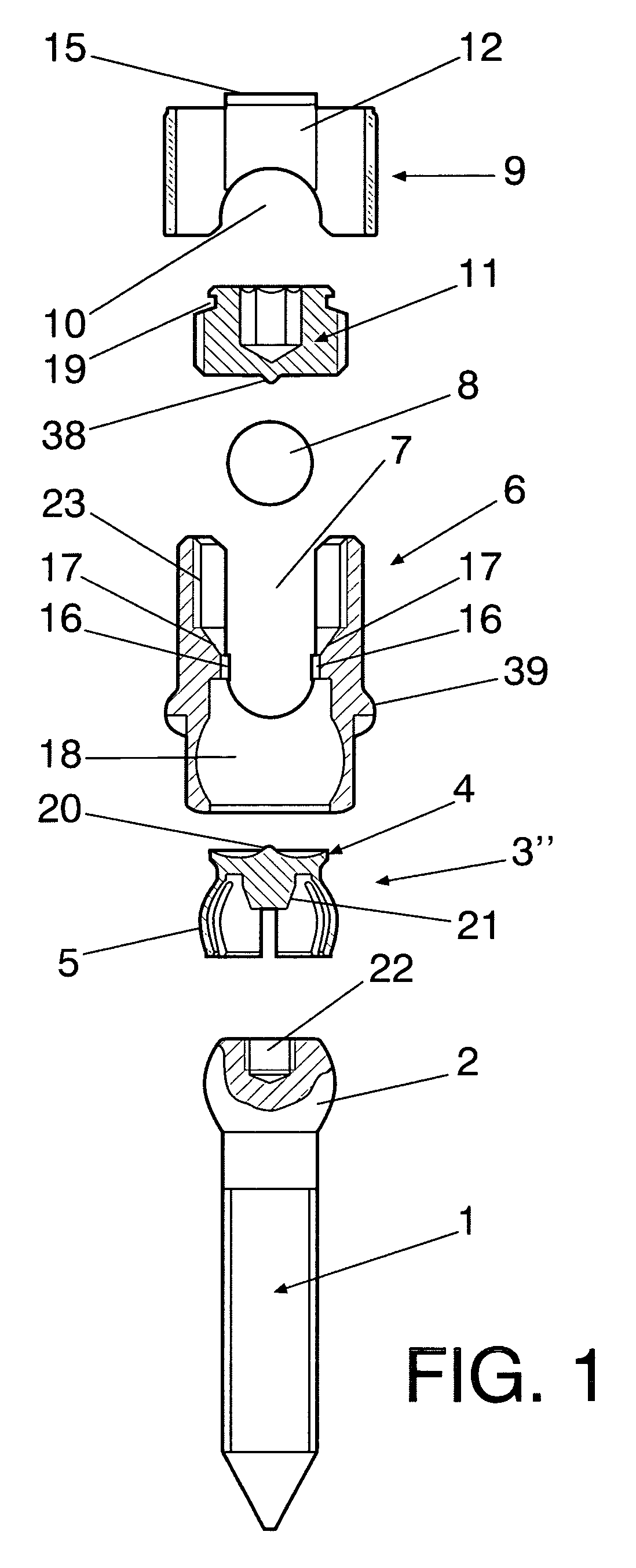
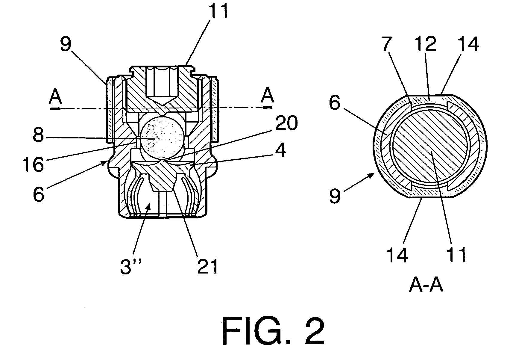
The fixation device basically consists of a pedicle screw with a partially spherical head, a flexible rosette that presses on and fixes the position of the head at a particular angle, a tulip that has two lateral notches opposite each other and a cavity that holds the rosette, a bar that constitutes the connection with other devices fixed to other vertebrae and w...


PUM


Abstract

Constitutes a pedicle screw (1), a rosette (3) that fixes the pedicle screw (1) to a tulip (6), a bar that constitutes the link with other devices and a locking cap (9) associated to the closing screw (11) that is threaded on the inside of the tulip (6) and fixes the position of the bar. The locking cap (9) incorporates protuberances (12) that fit on the tulip (6), guiding the set formed by the locking cap (9) and the closing screw (11) during the positioning and threading of the closing screw (11) on the tulip (6) pressing the bar (8) against the rosette (3). The outer face of the tulip (6) and the locking cap (9) present an essentially circular configuration that is interrupted by two opposite-facing flat indentations (13, 14) that contribute to reduce the width of the device in the axial direction of the bar (8).

Description

OBJECT OF THE INVENTIONThis invention belongs to the field of bone surgery and refers to a device that has been specially designed to immobilise two or more vertebrae in collaboration with another similar device linked to the same bar.The object of the invention consists of developing a first vertebral fixation device with optimised configuration that allow to adjust the various elements that make it up, particularly when it is being assembled on the bone, thereby ensuring that the elements are more firmly attached and that the system is stronger, while also aiming to minimise the space occupied by the device.A further object of the invention is the tool that is used to assemble and make the final adjustments to the elements that make up this first device, once it has been previously screwed to the bone.A still further object of the invention is a second vertebral fixation device that consists of a lateral connector that allows correcting lateral deviations between vertebrae.BACKGRO...

Claims


Application Information

Patent Timeline
Patent Type & Authority Patents(United States)
IPC IPC(8): A61B17/70H04W4/10
CPCA61B17/7032A61B17/7035A61B17/7037A61B17/7041A61B17/7091
Inventor ALVAREZ, LUIS MARQUEZ
Owner TRAIBER
Why Eureka
Try Eureka