Radio frequency identification tag

a radio frequency identification and tag technology, applied in the field of radio frequency identification (rfid) tags, can solve the problems of affecting the operation of the semi-passive rfid tag, the power of the signal received by the passive rfid tag is liable to be less than the required operating power, and the effective read distance is relatively short. to achieve the effect of strengthening the usage distance of the passive rfid tag

Inactive Publication Date: 2011-12-27
NAT TAIWAN UNIV OF SCI & TECH
View PDF9 Cites 18 Cited by
  • Summary
  • Abstract
  • Description
  • Claims
  • Application Information

AI Technical Summary

Benefits of technology

[0010]The present invention is directed to a radio frequency identification (RFID) tag, in which a passive RFID tag and a battery-assisted circuit are integrated to strengthen a usage distance of the passive RFID tag, and a filter is disposed in front of a demodulator for filtering a signal whose frequency is outside a frequency transmitted by a reader, so that a RFID tag decoding is less affected by multi-carrier.
[0015]According to the above descriptions, the present invention provides a novel RFID tag, in which the filter is used to filter a RF signal whose frequency is outside a frequency of a reader command of the reader, so that the problem that the reader command cannot be decoded due to inadequate modulation depth thereof can be resolved. Meanwhile, the RFID tag can use carriers of different frequencies to generate extra power, so that a read distance of the RFID tag can be further extended. In addition, a situation of inadequate modulation depth occurred under a multi-carrier environment can be avoided. Therefore, the read distance of the RFID tag can be effectively extended.

Problems solved by technology

However, when the battery is out of power, the semi-passive RFID tag cannot be normally operated.
However, since the operating power thereof comes from the RF signal sent by a reader, an effective read distance thereof is relatively short.
Meanwhile, due to an influence of a multipath fading effect, a power of the signal received by the passive RFID tag is liable to be less than the required operating power.
However, in a multi-carrier environment, a minimum amplitude difference required for receiving the reader command limits a performance of the tag read distance.

Method used


Image

  • Radio frequency identification tag
  • Radio frequency identification tag
  • Radio frequency identification tag

Examples


Embodiment Construction

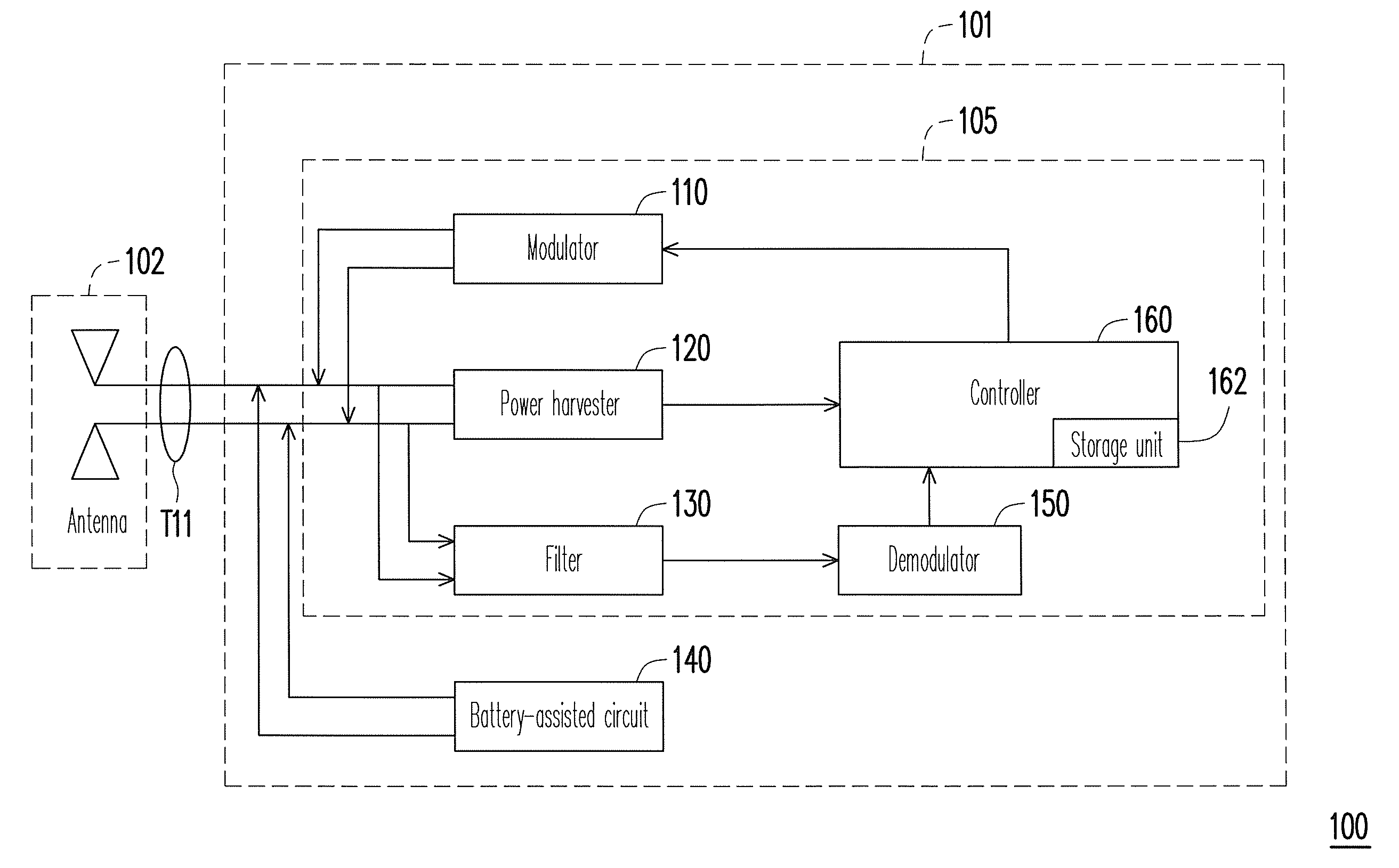
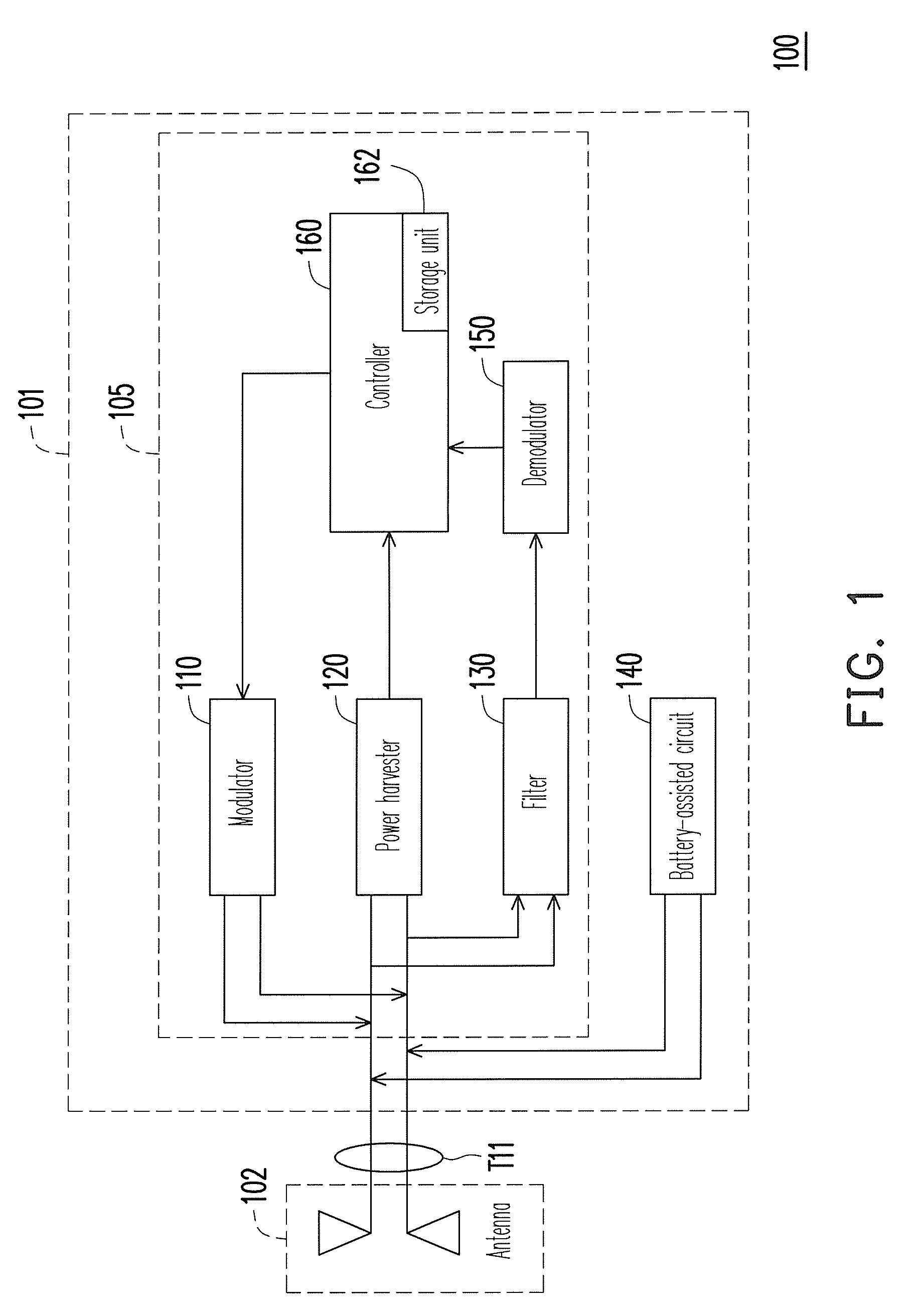
[0020]Referring to FIG. 1, FIG. 1 is a functional block diagram illustrating a radio frequency identification (RFID) tag according to an embodiment of the present invention. The RFID tag 100 includes a signal processing circuit 101 and an antenna 102. The signal processing circuit 101 includes a RF tag chip 105 and a battery-assisted circuit 140. The battery-assisted circuit 140 is coupled to a signal port T11 of the RF tag chip 105, and the signal port T11 has two ports. The RF tag chip 105 includes a modulator 110, a power harvester 120, a filter 130, a demodulator 150 and a controller 160. The modulator 110 is coupled between the signal port T11 and the controller 160. The power harvester 120 is coupled between the signal port T11 and the controller 160. The filter 130 is coupled between the demodulator 150 and the signal port T11, and another end of the demodulator 150 is coupled to the controller 160. The battery-assisted circuit 140 is also coupled to the signal port T11, wher...


PUM


Abstract

A battery-assisted radio frequency identification (RFID) tag having a battery-assisted circuit and a filter is provided. The battery-assisted circuit generates a radio frequency signal whose frequency is outside an operating frequency band of the RFID tag to supply additional power to the RFID tag. The filter filters the radio frequency signal output from the battery-assisted circuit before the RFID tag demodulates a reader command, so that a modulation depth of the read command is less affected by multi-carrier. By using the battery-assisted circuit and the filter, the RFID tag has a longer read range and is less affected by multipath fading effects.

Description

CROSS-REFERENCE TO RELATED APPLICATION[0001]This application claims the priority benefit of Taiwan application serial no. 98131581, filed on Sep. 18, 2009. The entirety of the above-mentioned patent application is hereby incorporated by reference herein and made a part of this specification.BACKGROUND OF THE INVENTION[0002]1. Field of the Invention[0003]The present invention relates to a radio frequency identification (RFID) tag. More particularly, the present invention relates to a batter-assisted tag in accordance with an EPCglobal class 1 generation 2 RFID standard.[0004]2. Description of Related Art[0005]As radio frequency identification (RFID) technique gradually becomes mature, and a price thereof decreases, application of the RFID technique is widespread. For example, a RFID tag is applied to a smart card (a chip card or an integrated circuit (IC) card) for providing convenience and security.[0006]Generally, the RFID tags are mainly grouped into passive, semi-passive and acti...

Claims


Application Information

Patent Timeline
Patent Type & Authority Patents(United States)
IPC IPC(8): H04Q5/22
CPCG06K19/0723
Inventor LIU, HSIN-CHINPENG, JHIH-GUO
Owner NAT TAIWAN UNIV OF SCI & TECH
Why Eureka
Try Eureka