Image display apparatus and image taking apparatus including the same

a technology of image display and image, which is applied in the field of image display apparatus and image taking apparatus, can solve the problems of increased number of pixel defects, difficult to produce pixels, and same problems as in the case of two-dimensional display elements, and achieves the effect of high precision and preferable quality

Inactive Publication Date: 2011-12-27
CANON KK
View PDF20 Cites 1 Cited by
  • Summary
  • Abstract
  • Description
  • Claims
  • Application Information

AI Technical Summary

Benefits of technology

[0018]An object of the present invention is to provide: an image display apparatus in which a synchronization light detecting means is disposed at a suitable position in the case where a surface to be scanned is two-dimensionally scanned with a light beam which is optically modulated based on image information and emitted from a light source means by using a scanning means which is oscillated and image information formed on the surface to be scanned is observed, so that a synchronization signal can be detected with high precision and a preferable quality image can be displayed for observation; and an image taking apparatus including the image display apparatus.

Problems solved by technology

That is, the number of pixel defects increases as the number of pixels increases.
A pixel size becomes relatively smaller than a size of the two-dimensional display element, so that it is hard to produce the pixels.
Therefore, the same problems as those in the case of the two-dimensional display element occur.
In U.S. Pat. No. 5,489,950 B (corresponding to JP 06-342126 A), since scanning light is not detected, sufficient precision is not obtained in some cases.
Further, since first and second light detectors are disposed in a region corresponding to angles other than an effective deflection angle within all deflection angles of a scanning means which is oscillated, when an interval between an optical path corresponding to the effective deflection angle and an optical path for a synchronization light detector is narrowed, an interference (overlapping) between the optical paths occurs to cause that a light quantity loss of an effective beam may occurs in some cases.
However, the configuration is complicated because the separate beams are used.

Method used


Image

  • Image display apparatus and image taking apparatus including the same
  • Image display apparatus and image taking apparatus including the same
  • Image display apparatus and image taking apparatus including the same

Examples


embodiment 1

[0050]Embodiment 1 of the present invention will be described below.

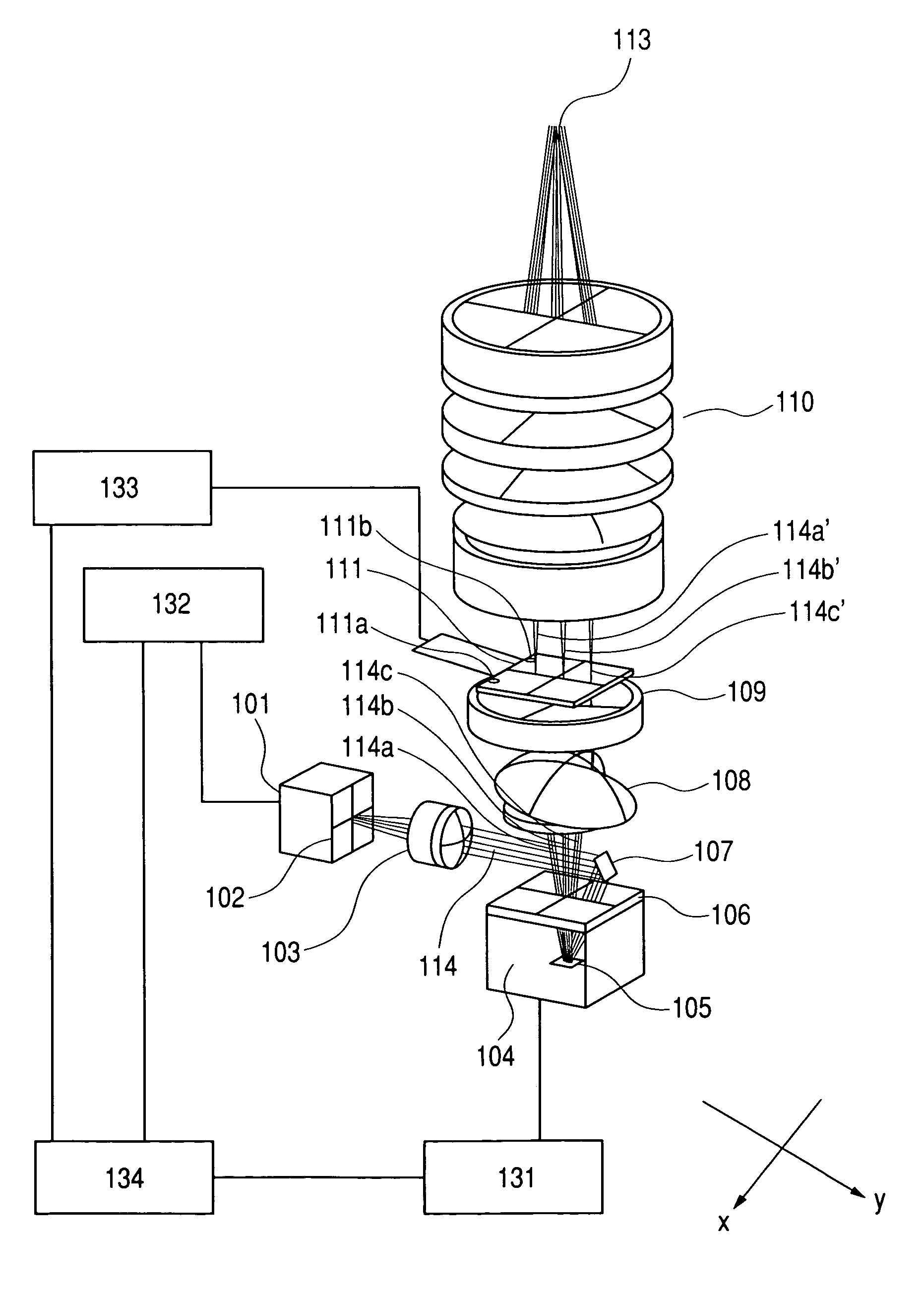
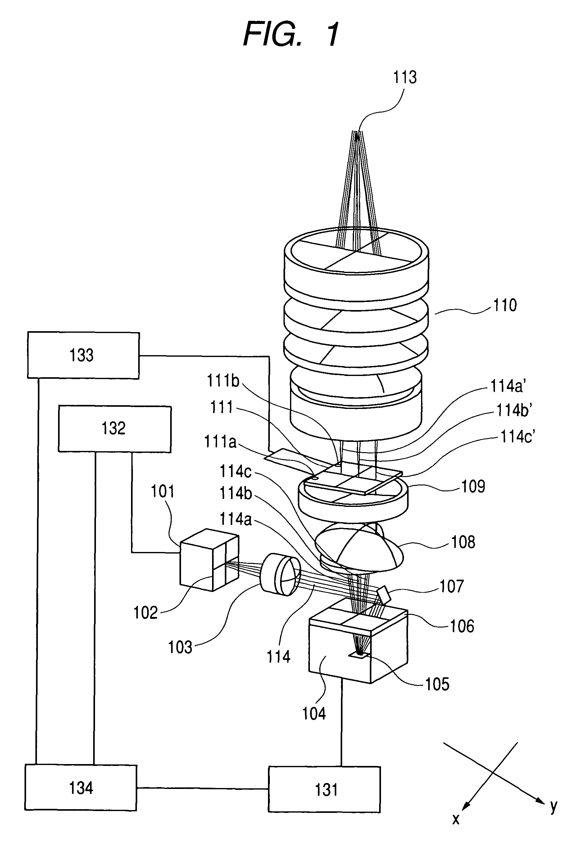
[0051]FIG. 1 is a schematic explanatory view showing a scanning image display apparatus used for an electronic view finder. FIG. 2 is a main part sectional view showing the image display apparatus of FIG. 1 in a vertical scanning direction. The entire structure of the image display apparatus will be described with reference to FIGS. 1 and 2.

[0052]A light beam including a plurality of color light beams, which is emitted from a light source means 101, transmits through a color combining optical system 102 for combining the plurality of color light beams, a condensing optical system 103 composed of a condenser lens, a collimator lens, and the like, a deflection mirror 107, and a cover glass member 106, and is incident on a scanning means 104 capable of performing two-dimensional scanning. The scanning means 104 includes a deflection mirror 105 produced using a MEMS technique and performs two-dimensional scanning with t...

embodiment 2

[0075]FIG. 12 is a main part schematic view showing an image display apparatus according to Embodiment 2 of the present invention. In this embodiment, a type of the synchronization light detecting means and the position thereof are different from those in Embodiment 1 shown in FIG. 1.

[0076]In FIG. 12, the same reference numerals are provided for the same elements as those indicated in Embodiment 1.

[0077]The same reference numerals as those in Embodiment 1 indicate the same functions and therefore the descriptions are omitted here.

[0078]In FIG. 12, reference numeral 127 denotes a synchronization light detecting means. In this embodiment, the synchronization light detecting means 127 is disposed within an over-scanning area on the surface to be scanned 109 in the vertical direction (y-direction). FIG. 13 shows an arrangement of the synchronization light detecting means 127. As shown in FIG. 13, the synchronization light detecting means 127 is disposed at the center of the over-scannin...

embodiment 3

[0082]FIG. 15 is a main part schematic diagram showing an image display apparatus according to Embodiment 3 of the present invention.

[0083]A scanning image display apparatus according to this embodiment is suitable to a projector in which a light beam from a light source means is scanned by a resonance type horizontal scanning means 203 and, for example, a galvano type vertical scanning means 207, which are separated from each other, so that an image is displayed for observation on a screen 220 serving as the surface to be scanned.

[0084]A light source means 201 is composed of a semiconductor laser or a wavelength conversion means using a semiconductor laser as a base. In FIG. 15, the single light source means 201 is shown, however, the light source means 201 can be also composed of, for example, a plurality of light source means for emitting red light, blue light, and green light. The light source means 201 is electrically connected with a light source control circuit 223 and-optica...


PUM


Abstract

Provided is image display apparatus, in which a surface to be scanned is two-dimensionally scanned with a light beam which is modulated based on image information and emitted from a light source means and an image formed on the surface to be scanned is observed through an optical system, wherein a synchronization light detection device to obtain synchronization signal related to a scanning start position on the surface to be scanned is disposed on the surface to be scanned, on the vicinity thereof, or on a surface optically conjugate therewith, so that a synchronization signal can be detected with high precision and a preferable quality image can be displayed for observation, and image taking apparatus including the image display apparatus.

Description

BACKGROUND OF THE INVENTION[0001]1. Field of the Invention[0002]The present invention relates to an image display apparatus and an image taking apparatus including the same, which are suitable to, for example, the case where an image is displayed by two-dimensionally raster-scanning a surface to be scanned with a light beam which is emitted from a light source means and optically modulated based on image information and the image formed on the surface to be scanned is observed.[0003]2. Related Background Art[0004]In an image display apparatus such as a head-mount type display apparatus or an electronic view finder system used for a digital camera or the like, a two-dimensional display element such as a transmission type liquid crystal element, a reflection type liquid crystal element, or an organic EL element and an eyepiece optical system are combined with each other so as to display and observe an image formed on the two-dimensional display element as a virtual image through the e...

Claims


Application Information

Patent Timeline
Patent Type & Authority Patents(United States)
IPC IPC(8): G09G5/00G02B26/08G02B26/10G02B27/02H04N5/225H04N5/74
CPCG02B26/101H04N5/2251H04N5/7491G02B26/0833
Inventor KOBAYASHI, SHUICHIMAJIMA, MASAOKANDORI, ATSUSHIYAMAMOTO, AKIRA
Owner CANON KK
Why Eureka
Try Eureka