Flow control in a cellular communication system

low control technology, applied in the field of flow control in a cellular communication system, can solve the problems of unrecoverable data loss, substantial delay, limited resource of base station buffer memory, etc., and achieve the effect of efficient flow control, efficient flow control, and efficient flow control

Inactive Publication Date: 2011-12-27
SONY CORP
View PDF17 Cites 16 Cited by
  • Summary
  • Abstract
  • Description
  • Claims
  • Application Information

AI Technical Summary

Benefits of technology

[0028]The invention may allow highly effective flow control for a data flow between the RNC and the base station. The flow control may e.g. allow reduced latency, reduced buffer underflow / overflow, low signalling overhead and / or a simplified implementation. The performance of the cellular communication system as a whole may be improved and / or the service provided to users may be improved. In particular, the invention may allow a highly efficient flow control for a shared scheduling function between the base station and the RNC.
[0069]According to an optional feature of the invention, the RNC further comprises means for replacing an existing transfer allowance when a transfer allowance is received from the base station. This may allow a practical implementation and / or efficient flow control. The feature may furthermore provide compatibility with existing systems such as UMTS. In particular, when a new transfer allowance is received the current allowance may be overwritten by the new value.

Problems solved by technology

The impact of this on RLC AM (Acknowledged Mode—using retransmissions of lost data packets) radio bearers is one of increased latency—the RLC protocol can recover the loss using retransmissions but this introduces a substantial delay.
However, for UM (Unacknowledged Mode—no retransmissions) radio bearers the data is unrecoverably lost.In certain implementations, base station buffer memory may be a limited resource.
However, these requirements tend to be conflicting requirements and a trade off between the requirements is typically required.
However, known algorithms tend to be suboptimal and to provide performance and / or trade offs which are undesirable.

Method used


Image

  • Flow control in a cellular communication system
  • Flow control in a cellular communication system
  • Flow control in a cellular communication system

Examples


Embodiment Construction

[0080]The following description focuses on embodiments of the invention applicable to a UMTS cellular communication system and in particular to HSDPA communication in a cellular communication system. However, it will be appreciated that the invention is not limited to this application but may be applied to many other communication systems and services.

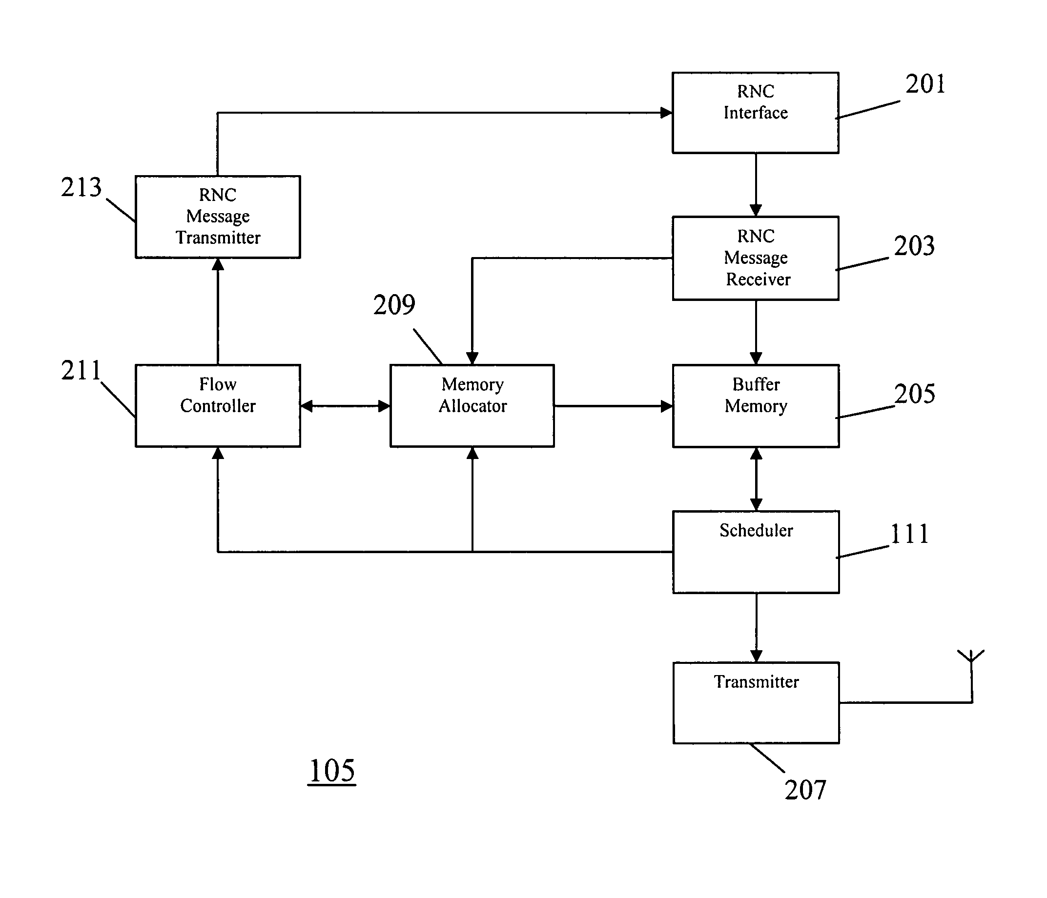
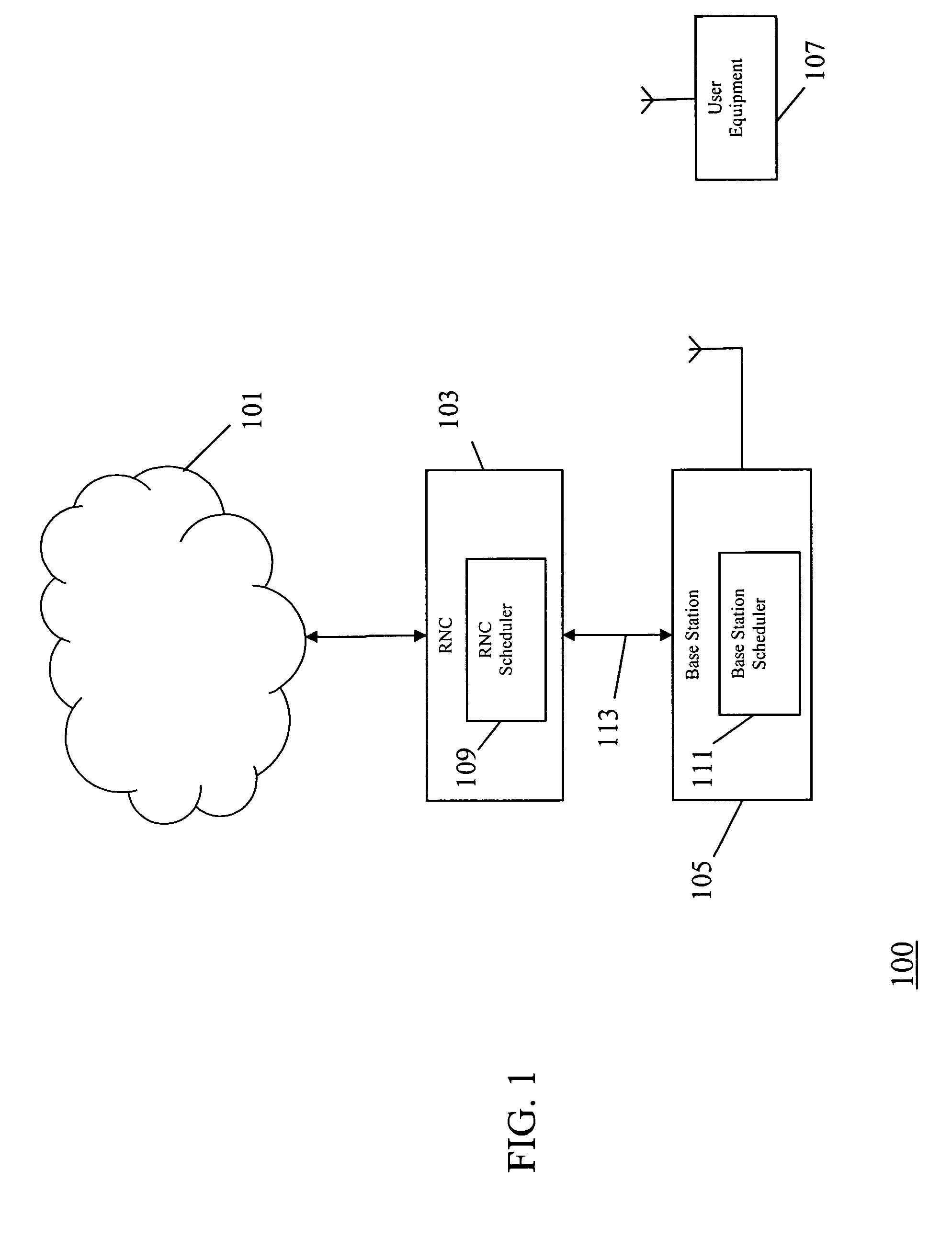
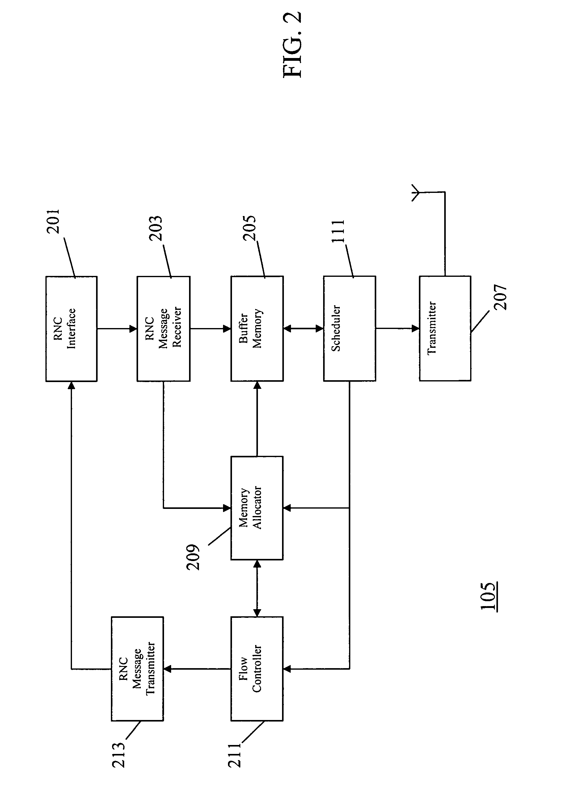
[0081]FIG. 1 illustrates an example of a cellular communication system 100 in accordance with some embodiments of the invention. The cellular communication system 100 is particularly a UMTS cellular communication system supporting HSDPA services. The UMTS system 100 comprises a core network 101 which is coupled to a number of RNCs of which one RNC 103 is shown. The RNC 103 is coupled to a number of base stations of which one base station 105 is shown. The base station 105 supports an HSDPA service for a first user equipment 107. It will be appreciated that the base station 105 typically will support a large number of user equipments si...


PUM


Abstract

A base station comprises an RNC message receiver which receives data packets from a Radio Network Controller, RNC. The data packets are transmitted over air interface channels by a transmitter. The base station includes buffer memory for buffering the data packets prior to transmission, a scheduler for scheduling the data packets for transmission over the air interface channels, and a memory allocator for determining a first memory allocation of the buffer memory for a first air interface communication with a first user equipment. The base station further includes a flow controller for determining a transfer allowance for transferring of data from the RNC to the base station in response to the first memory allocation and a current buffer memory usage of the first air interface communication. The transfer allowance is transmitted to the RNC by an RNC message transmitter for achieving an efficient flow control.

Description

FIELD OF THE INVENTION[0001]The invention relates to flow control in a cellular communication system and in particular to flow control between a Radio Network Controller and a base station.BACKGROUND OF THE INVENTION[0002]In a cellular communication system, a geographical region is divided into a number of cells each of which is served by a base station. The base stations are interconnected by a fixed network which can communicate data between the base stations. A mobile station is served via a radio communication link by the base station of the cell within which the mobile station is situated. Communication from a mobile station to a base station is known as uplink, and communication from a base station to a mobile station is known as downlink.[0003]The fixed network interconnecting the base stations is operable to route data between any two base stations, thereby enabling a mobile station in a cell to communicate with a mobile station in any other cell. In addition, the fixed netw...

Claims


Application Information

Patent Timeline
Patent Type & Authority Patents(United States)
IPC IPC(8): G01R31/08H04M1/00H04B1/56H04W28/10H04W28/12H04W28/14H04W72/12
CPCH04L12/5693H04L47/10H04L47/527H04L49/90H04W28/10H04W28/12H04W28/14H04W72/1252H04W92/12H04L47/50H04W72/52H04B7/155
Inventor LEGG, PETER JONATHON
Owner SONY CORP
Why Eureka
Try Eureka