Image forming device with open/close cover and manual paper feeding tray

a technology of open/close cover and paper feeding tray, which is applied in the direction of thin material processing, instruments, article separation, etc., can solve the problems of losing the support of the main body side of the paper feeding tray, and achieving the effect of smooth opening/closed

Inactive Publication Date: 2012-01-03
MURATA MASCH LTD
View PDF11 Cites 23 Cited by
  • Summary
  • Abstract
  • Description
  • Claims
  • Application Information

AI Technical Summary

Benefits of technology

[0009]In order to overcome the problems described above, preferred embodiments of the present invention provide a configuration enabling the open / close cover to be smoothly opened / closed even when using the manual paper feeding tray in the image forming device that is configured so that the rotation shaft of the open / close cover and the rotation shaft of the manual paper feeding tray are different.
[0011]Thus, the excessive rotation can be prevented by the tray side contacting portion and the main body side contacting portion even if the open / close cover is opened with the manual paper feeding tray opened, the second rotation shaft of the manual paper feeding tray moves with the movement of the open / close cover, and the manual paper feeding tray is in a freely rotatable state. Therefore, the excessively rotated manual paper feeding tray is prevented from interfering with other members and preventing the open / close cover from being closed. Since the configuration of regulating the rotation by having the tray side contacting portion contact with the main body side contacting portion is adopted, the excessive rotation of the manual paper feeding tray can be reliably prevented regardless of the position of the open / close cover. The degree of freedom in the arrangement of the manual paper feeding tray can be enhanced since the paper feed tray is attached to the open / close cover with the shaft lines of the first rotation shaft and the second rotation shaft being different.
[0013]A sheet of recording paper is thus prevented from dropping from the distal end side of the manual paper feeding tray even if the open / close cover is opened with the recording paper set in the manual paper feeding tray and the second rotation shaft of the manual paper feeding tray moves.
[0015]The manual paper feeding tray thus can be held at a stable and accurate position by the positioning unit, and the operation of sending the recording paper set in the manual paper feeding tray to the interior of the main body can be smoothly carried out.
[0017]A simple configuration capable of reliably regulating the rotation of the manual paper feeding tray thus can be realized.
[0019]Thus, the usage position of the manual paper feeding tray can be more accurately positioned without the tray side contacting portion and the main body side contacting portion getting in the way.

Problems solved by technology

In such a configuration, however, when the open / close cover is rotated with the manual paper feeding tray opened, the manual paper feeding tray separated from the usage position loses the support of the main body side and becomes freely rotatable.

Method used


Image

  • Image forming device with open/close cover and manual paper feeding tray
  • Image forming device with open/close cover and manual paper feeding tray
  • Image forming device with open/close cover and manual paper feeding tray

Examples


Embodiment Construction

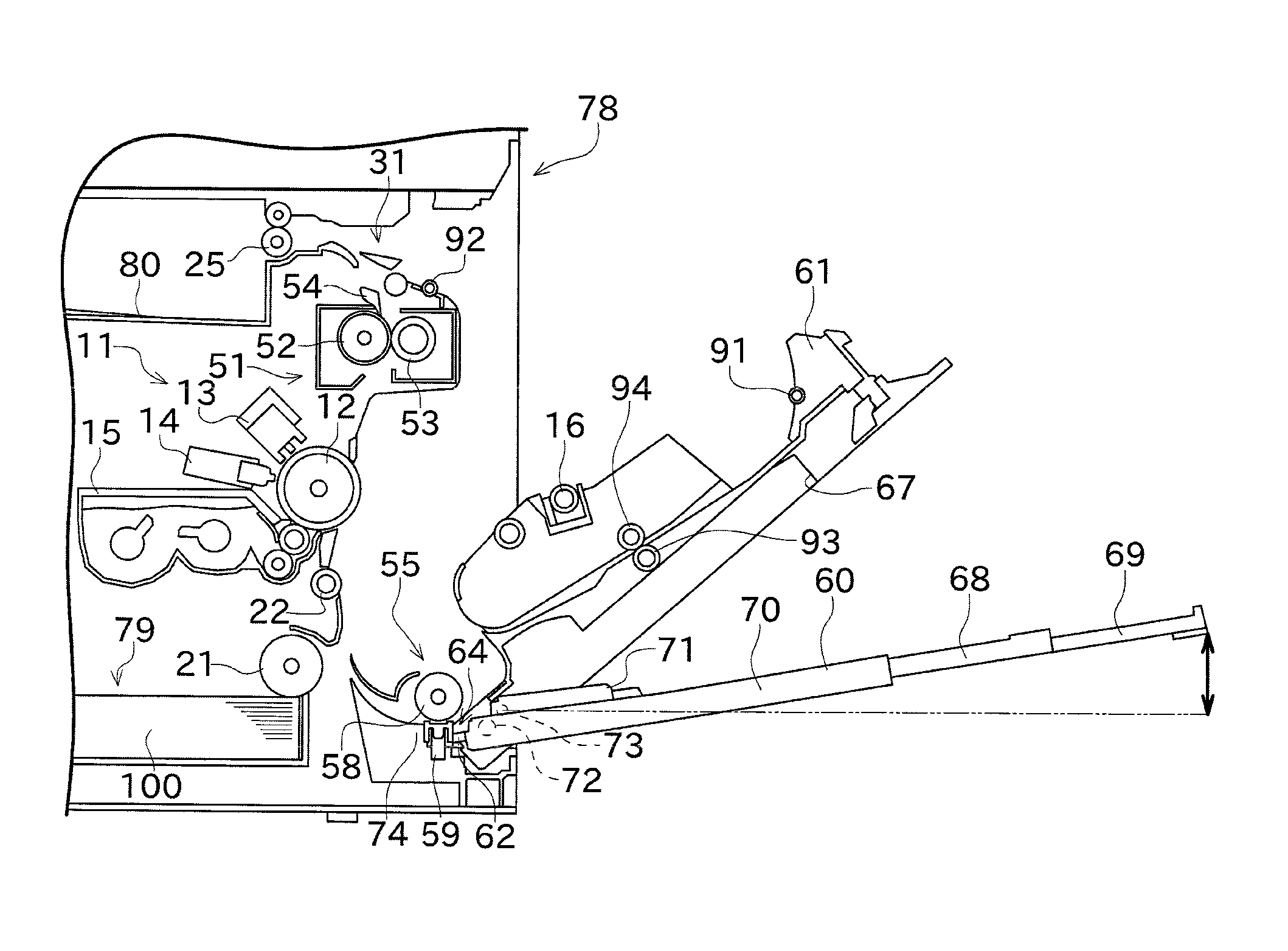
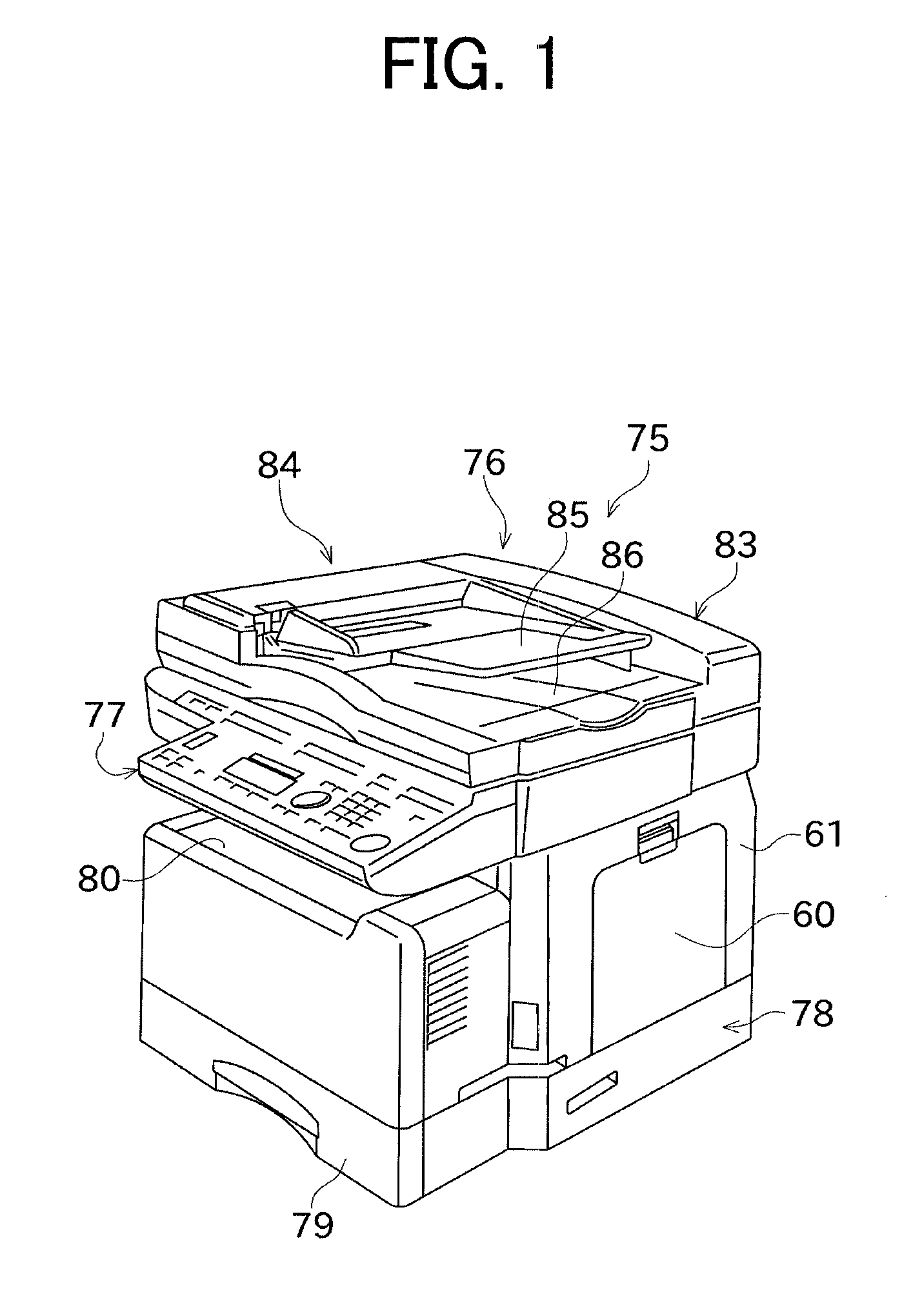
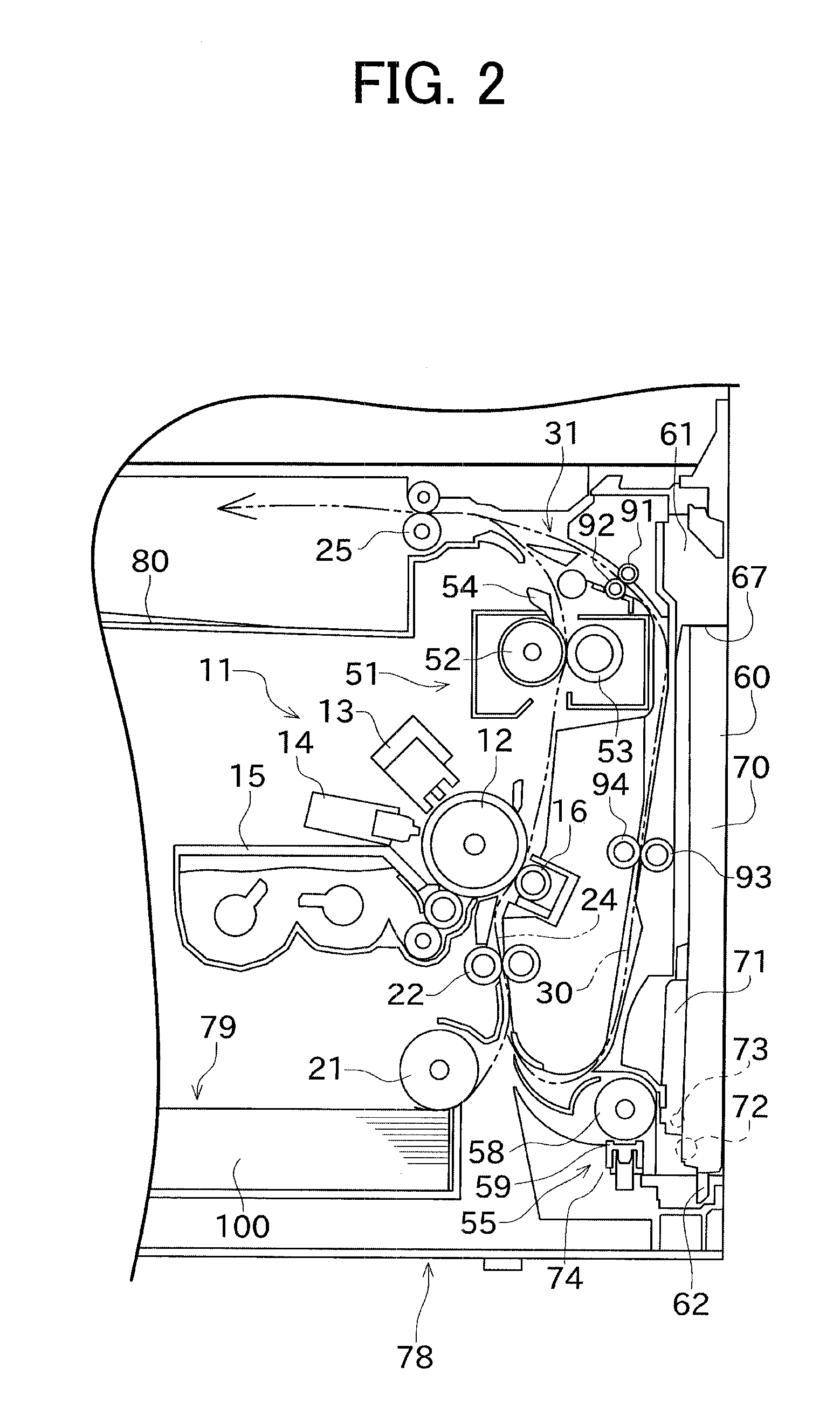
[0032]Preferred embodiments of the present invention will now be described. FIG. 1 is a perspective view of an outer appearance of a copy-facsimile multifunction peripheral 75 serving as an image forming device according to one preferred embodiment of the present invention. FIG. 2 is a cross-sectional view schematically illustrating one portion of the internal configuration of a main body 78 of the multifunction peripheral 75. In the following description, the direction orthogonal to the direction of transporting a sheet of paper 100 (transporting direction) is sometimes referred to as a width direction.

[0033]As illustrated in FIG. 1, the copy facsimile multifunction peripheral 75 includes an image reading unit 76, an operation panel 77, the main body 78, and a paper feed cassette 79. The configuration of each unit will be described below.

[0034]The image reading unit 76 is provided to read documents, and includes a scanner unit (not illustrated) serving as a reading unit, a platen c...


PUM


Abstract

A multifunction peripheral includes a main body, a jam access cover, and a manual paper feeding tray. The jam access cover can expose the interior of the main body by being rotated. The manual paper feeding tray is attached to the jam access cover so as to be rotatable with a tray rotation shaft at a position that is different from a jam access cover rotation shaft as a center. A projection is arranged on the manual paper feeding tray so as to contact with a recess on the main body side to regulate the rotation of the manual paper feeding tray when the jam access cover is opened. The manual paper feeding tray includes a distal end that is located a higher position than the jam access cover rotation shaft when the projection contacts with the recess.

Description

[0001]This application claims priority under 35 U.S.C. 119 to Japanese Patent Application No. 2009-156926, filed on Jul. 1, 2009, which application is hereby incorporated by reference in its entirety.BACKGROUND OF THE INVENTION[0002]1. Field of the Invention[0003]The present invention relates to an image forming device, and specifically, to an open / close cover for exposing the interior of the main body and a manual paper feeding tray attached to the open / close cover.[0004]2. Description of the Related Art[0005]A configuration of attaching the open / close cover, which is rotatable with respect to the main body, to remove the paper that caused jamming (paper jam) in the interior of the main body in the image forming device is conventionally known. A manual paper feeding tray is sometimes attached to the open / close cover in such an image forming device. This type of image forming device is disclosed in Japanese Laid-Open Patent Publication No. 2008-83442.[0006]Japanese Laid-Open Patent ...

Claims


Application Information

Patent Timeline
Patent Type & Authority Patents(United States)
IPC IPC(8): B65H3/44
CPCB65H5/26G03G21/1695G03G21/1633G03G15/6514B65H2402/44B65H2405/1117B65H2407/21B65H2801/06G03G2215/00392G03G2215/00544G03G2221/1675G03G2221/169
Inventor OHTSUKI, RYOHEI
Owner MURATA MASCH LTD
Why Eureka
Try Eureka