
Demagnetizable electromagnetic door lock

Inactive Publication Date: 2007-02-01
CHANG CHEN FEI
View PDF2 Cites 0 Cited by
  • Summary
  • Abstract
  • Description
  • Claims
  • Application Information

AI Technical Summary

Benefits of technology

[0007] The primary objective of the present invention is to provide a demagnetizable electromagnetic door lock, which can overcome the problem of residual magnetization of the electromagnetic coil and can thus be smoothly opened / closed.
[0008] In order to realize the objective above, a demagnetizable electromagnetic door lock in accordance with the present invention is actuated by generating or degenerating magnetic force of an electromagnetic coil and comprises a magnetic field direction driving circuit electrically connected to the electromagnetic coil. Under the control of a controller, after the magnetic field direction driving circuit is applied to eliminate the residual magnetic force of the electromagnetic coil, the door lock can work smoothly in due course.

Problems solved by technology

However, in an operation of this conventional electromagnetic door lock, a hysteresis phenomenon might appear in a silicon steel core coupling with the electromagnetic coil and thus results in a failure of opening / closing the door lock.
It could be an awful experience if no substitutive key is available on hand.
Silicon steel sheet is rather expensive, so iron block is often used for substituting silicon steel sheet as a core.
However, the substitution of the iron block undoubtedly worsens the hysteresis loop.

Method used


Image

  • Demagnetizable electromagnetic door lock
  • Demagnetizable electromagnetic door lock
  • Demagnetizable electromagnetic door lock

Examples


Embodiment Construction

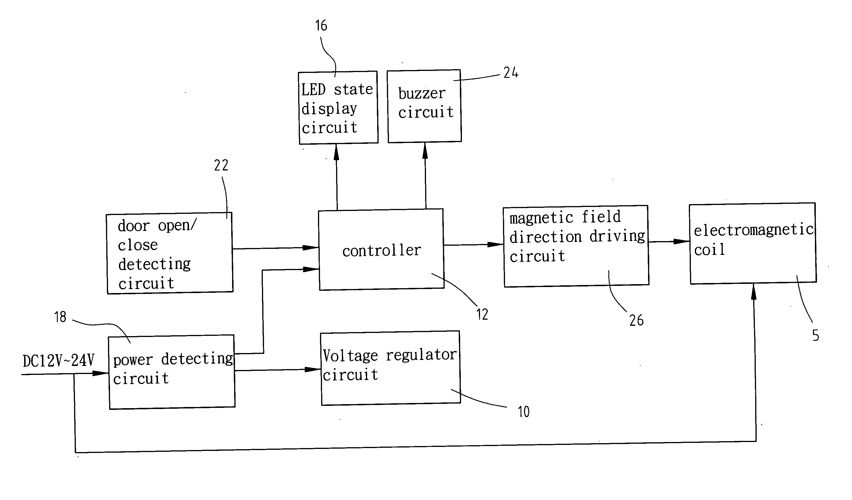
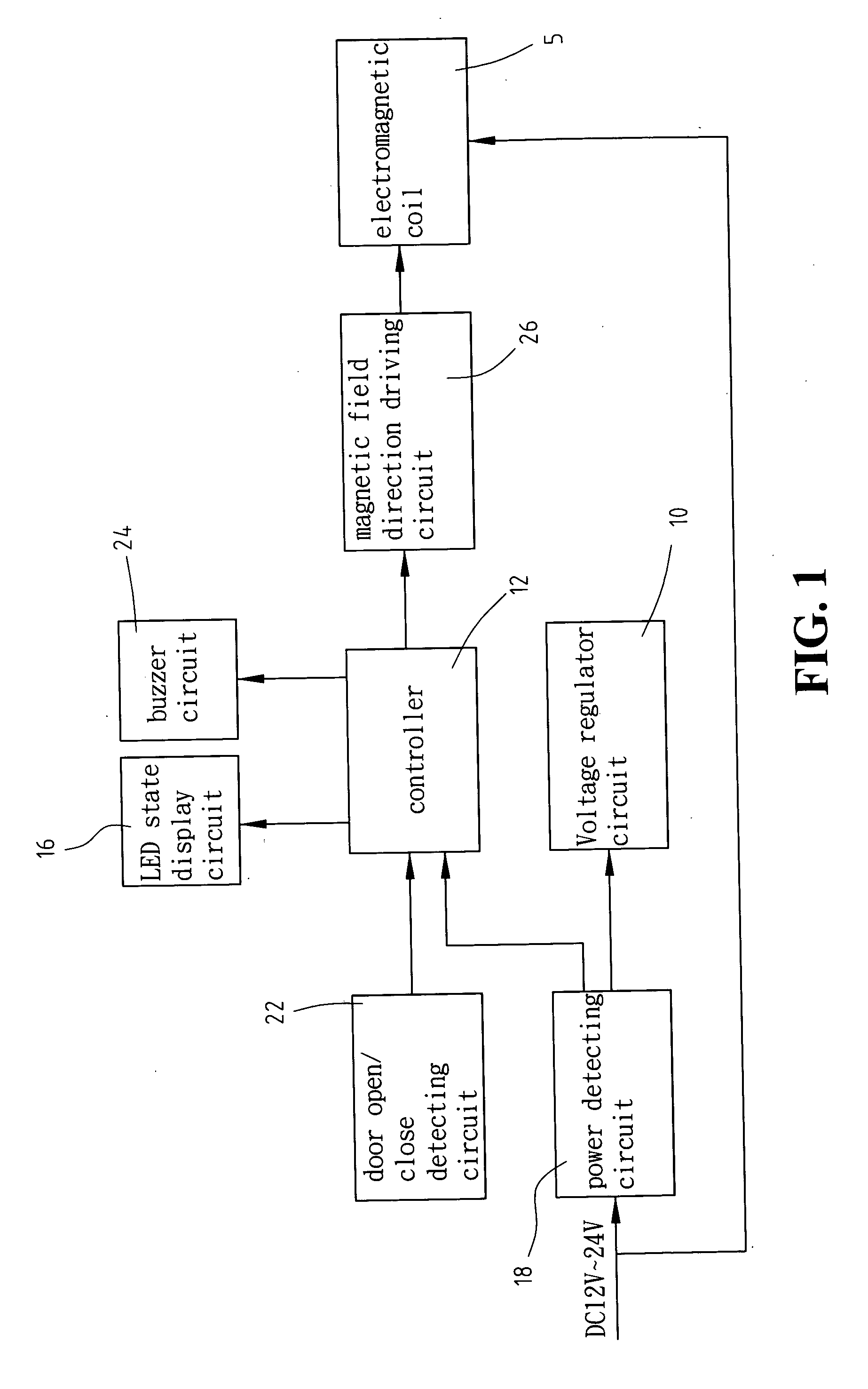
[0013] Referring to FIG. 1, a demagnetizable electromagnetic door lock in accordance with the present invention is provided with a magnetic field direction driving circuit 26 electrically connected to an electromagnetic coil 5. First the operation of a conventional electromagnetic door lock is described, and then a role of the magnetic field direction driving circuit 26 played in the demagnetizable electromagnetic door lock of the present invention is illustrated.

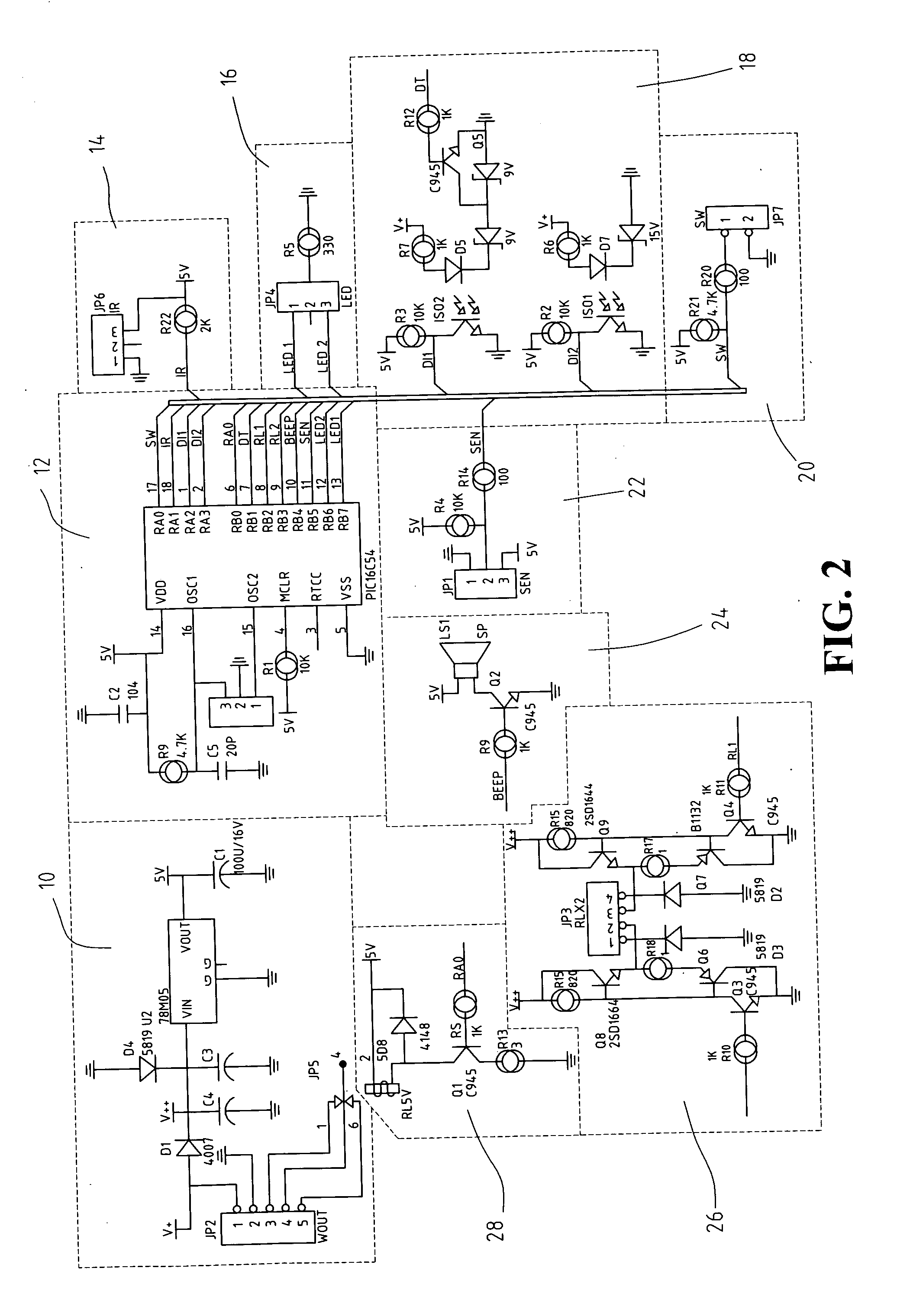
[0014] When a controller 12 connected with a power detecting circuit 18 and a voltage regulator circuit 10 is ready for work and receives a command from an external control signal circuit 14 (refer to FIG. 2) for opening or closing the door lock, the controller 12 actuates the door lock to be opened or closed and simultaneously starts a buzzer circuit 24 and an LED state display circuit 16 according to magnetization or demagnetization of the electromagnetic coil 5.

[0015] In order to solve the hysteresis phenomenon of the ...


PUM


Abstract

A demagnetizable electromagnetic door lock is actuated by generating or degenerating magnetic force of an electromagnetic coil. A magnetic field direction driving circuit is electrically connected to the electromagnetic coil. Under the control of a controller, after the magnetic field direction driving circuit is applied to eliminate the residual magnetic force of the electromagnetic coil, the door lock can work smoothly in due course.

Description

BACKGROUND OF THE INVENTION [0001] 1. Field of the Invention [0002] The present invention relates generally to an electromagnetic door lock, and more particularly to a demagnetizable electromagnetic door lock, which provides with a magnetic field direction driving circuit to eliminate residual magnetization of an electromagnetic coil. [0003] 2. The Prior Arts [0004] A conventional electromagnetic door lock applies an electromagnetic driving manner to open / close a door lock. Its executing mechanism may be classified as two groups: an electromagnetic coil type and a DC motor type. These two types of executing mechanism can reverse the motion direction of a lock member by means of changing its DC polarity, and thereby perform a door lock open / close operation. [0005] However, in an operation of this conventional electromagnetic door lock, a hysteresis phenomenon might appear in a silicon steel core coupling with the electromagnetic coil and thus results in a failure of opening / closing t...

Claims


Application Information

Patent Timeline
IPC IPC(8): H01H47/00
CPCH01F13/00E05B47/00
Inventor CHANG, CHEN-FEI
Owner CHANG CHEN FEI
Learn More