Multi-joint slider device

Active Publication Date: 2015-07-02
HYUNDAI MOTOR CO LTD
View PDF21 Cites 0 Cited by
  • Summary
  • Abstract
  • Description
  • Claims
  • Application Information

AI Technical Summary

Benefits of technology

[0011]Various aspects of the present invention are directed to providing a multi-joint slider device

Problems solved by technology

In the meantime, since the related art slider device of the cabin opening/closing door only has a linear rail extended in a length direction of the vehicle and a width direction of the cabin opening/closing door, and a linear slider only mova

Method used


Image

  • Multi-joint slider device
  • Multi-joint slider device
  • Multi-joint slider device

Examples


Embodiment Construction

[0040]Reference will now be made in detail to various embodiments of the present invention(s), examples of which are illustrated in the accompanying drawings and described below. While the invention(s) will be described in conjunction with exemplary embodiments, it will be understood that the present description is not intended to limit the invention(s) to those exemplary embodiments. On the contrary, the invention(s) is / are intended to cover not only the exemplary embodiments, but also various alternatives, modifications, equivalents and other embodiments, which may be included within the spirit and scope of the invention as defined by the appended claims.

[0041]Hereinafter, a multi-joint slider device in accordance with an exemplary embodiment of the present invention will be described with reference to the attached drawings.

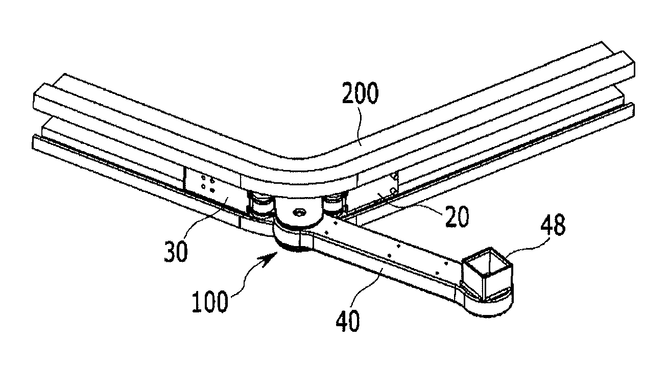
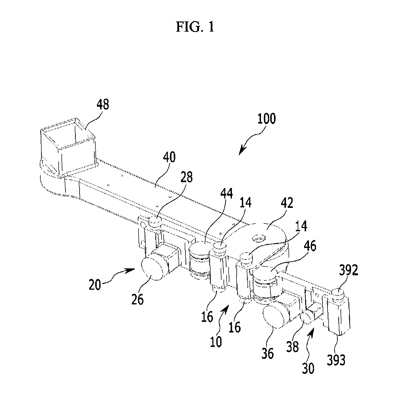
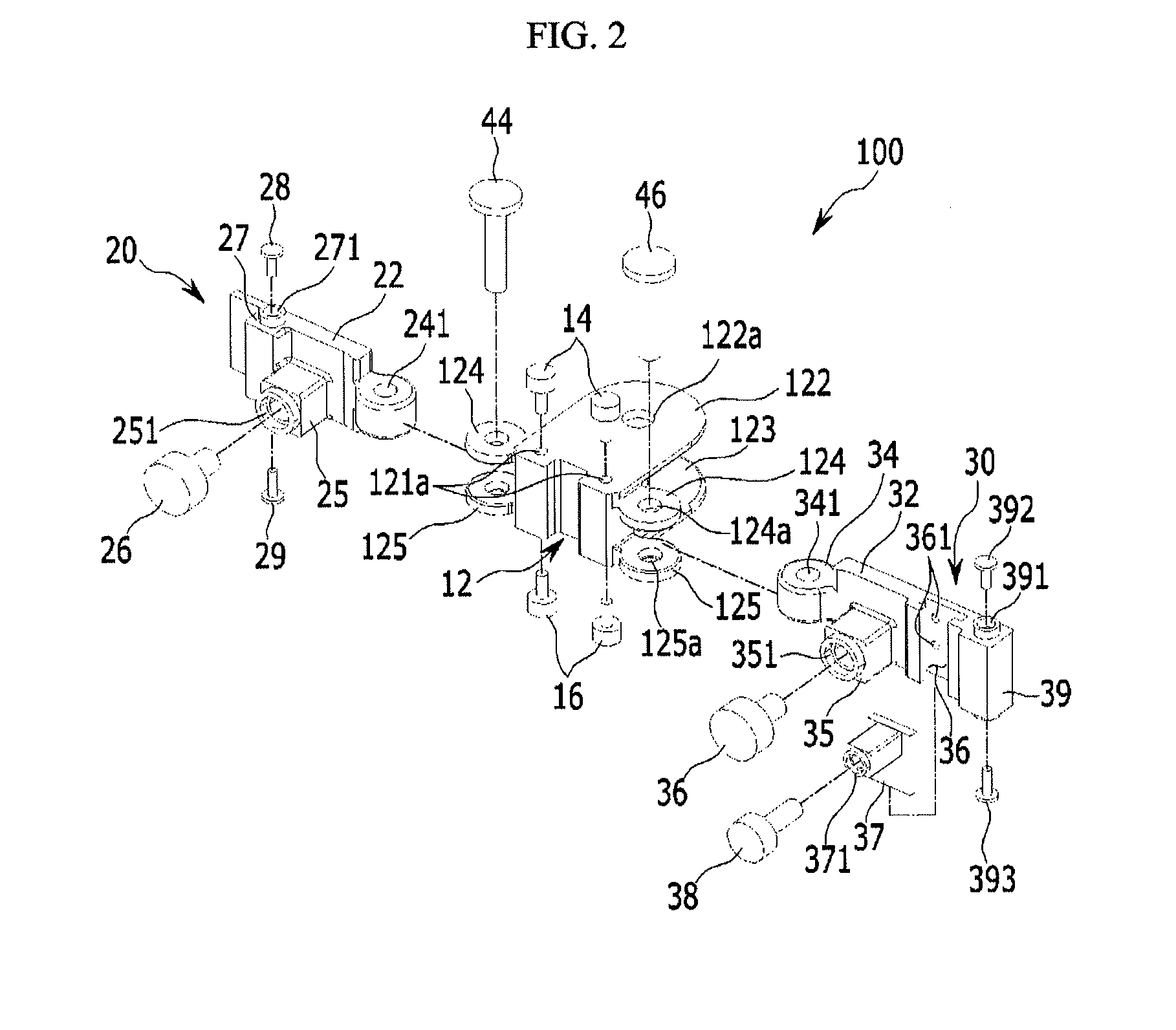
[0042]Referring to FIGS. 1 and 2, the multi-joint slider device in accordance with an exemplary embodiment of the present invention may include a multi-joint s...


PUM


Abstract

A multi joint slider device may include a center slider arranged at a center in a length direction thereof, the center slider having at least one roller, a front slider arranged in front of the center slider connected thereto with a first joint to enable relative rotation, the front slider having at least one roller, and a rear slider arranged in rear of the center slider connected thereto with a second joint to enable relative rotation, the rear slider having at least one roller, thereby permitting smooth rolling and sliding on the rail having a curved portion.

Description

CROSS-REFERENCE TO RELATED APPLICATION[0001]The present application claims priority to and the benefit of Korean Patent Application No. 10-2013-0164110 filed on Dec. 26, 2013, the entire contents of which is incorporated herein for all purposes by this reference.BACKGROUND OF THE INVENTION[0002]1. Field of the Invention[0003]The present invention relates to a multi-joint slider device. More particularly, the present invention relates to a multi-joint slider device having two or more than two joints which can roll along a rail curved at a predetermined angle, easily.[0004]2. Description of Related Art[0005]In general, the vehicle has a predetermined sized cabin formed therein for boarding of a driver and accompanying occupants therein, and cabin opening / closing doors are mounted to the vehicle body for opening / closing the cabin.[0006]In general, in a case of a passenger vehicle, though the cabin opening / closing doors are rotatably mounted to the vehicle body with hinges, in a case of...

Claims


Application Information

Patent Timeline
IPC IPC(8): E05D15/06B60J5/06
CPCB60J5/06E05D15/0621E05D15/101E05Y2201/64E05Y2900/531B60J5/14E06B9/02
Inventor CHOI, JAE HONG
Owner HYUNDAI MOTOR CO LTD
Why Eureka
Try Eureka