

Motor vehicle body
A technology of automobile body and plate, applied in the direction of vehicle parts, connecting members, thin plate connection, etc., can solve problems such as twisting, bending of lining elements, damage and so on
- Summary
- Abstract
- Description
- Claims
- Application Information
AI Technical Summary
Problems solved by technology
Method used
Image

Examples
Embodiment Construction
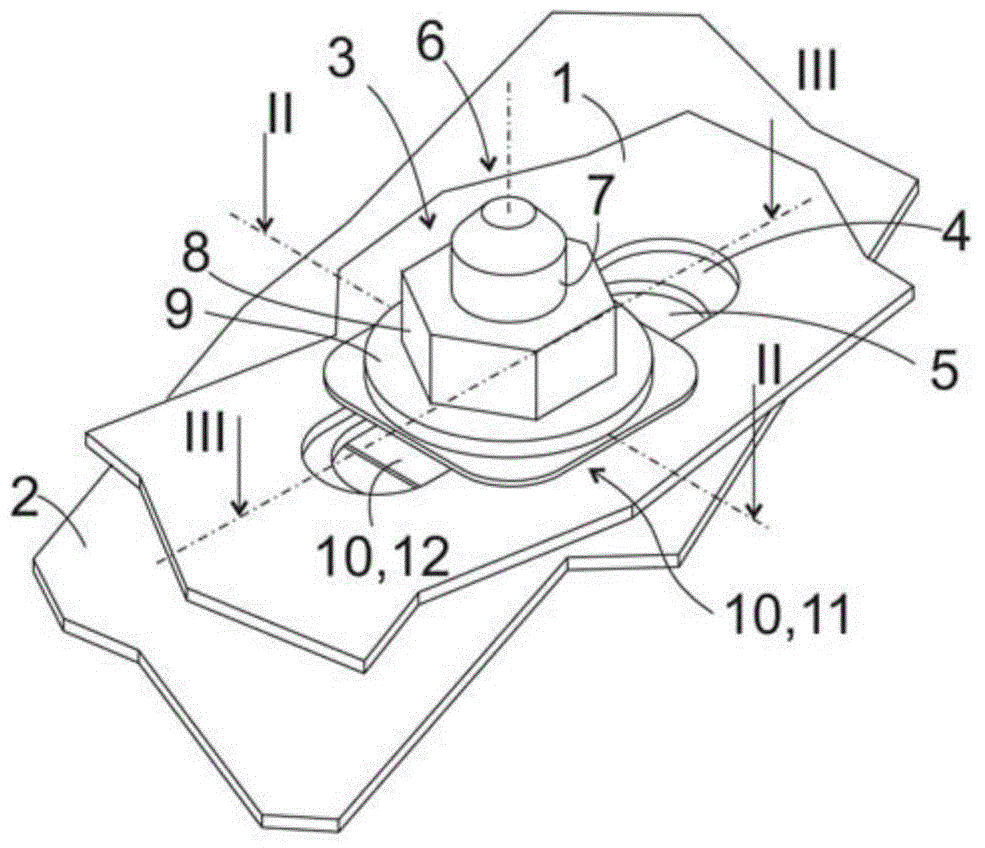
[0022] figure 1 A perspective view of a section of a first panel 1 and a second panel 2 is shown, clamped and fixed by a connection assembly 3 extending through the panels 1, 2 slotted holes 4,5. The longitudinal axes of the elongated holes 4, 5 are parallel to each other and are oriented along the plane marked III-III.
[0023] The panel 1 made of plastic, in particular fiber-reinforced plastic, is part of a lining element of a motor vehicle body which is not visible from the outside in the assembled vehicle. The lining element can be, for example, a fender, a door, a lid or the like. In contrast, the panel 2 is made of metal, in particular sheet steel, and is part of the supporting structure of the vehicle body. In particular, the second plate part can be a part of the frame rail or a frame part fastened to the frame rail.
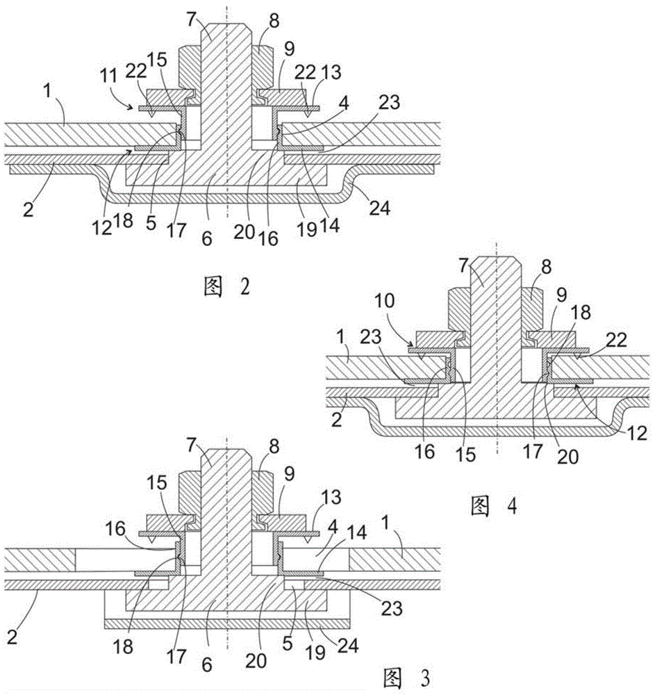
[0024] The connection assembly 3 here comprises bolts 6 (however from figure 1 Only the tip of the screw 7 can be seen in ), the nut 8 screwed on t...
PUM
 Abstract
Description
Claims
Application Information