Driving support device, driving support method and computer program

a technology of driving support and support device, which is applied in the direction of pedestrian/occupant safety arrangement, vehicular safety arrangement, television system, etc., can solve the problems of driver making erroneous judgments, inability to display the image captured by the camera at the same time that the image is captured, etc., to improve driving safety, and accurately display the actual blind spot region

Inactive Publication Date: 2012-01-03
AISIN AW CO LTD
View PDF15 Cites 30 Cited by
  • Summary
  • Abstract
  • Description
  • Claims
  • Application Information

AI Technical Summary

Benefits of technology

[0009]Accordingly, an objective of the present invention is to solve the aforementioned problems of the related art, and to provide a driving support device, a driving support method and a computer program capable of accurately displaying the actual blind spot region of a vehicle even when there is a time lag between the point in time when the image is captured and the point in time when the captured image is displayed, by extracting an image, corresponding to the blind spot region of the vehicle after a predetermined period of time from when the captured image was captured, and outputting the extracted image.
[0010]As noted above, the driving support device of the present invention makes it possible to accurately display an actual blind spot region of a vehicle even when there is a time lag between, for example, the point in time when an image is captured and the point in time when the captured image is displayed, by extracting an image corresponding to the blind spot region of the vehicle after a predetermined period of time from when the image is captured and outputting the captured image. Accordingly, actual circumstances around the periphery of the vehicle and the display of the periphery of the vehicle will not differ from each other, enabling a driver to make appropriate judgments.
[0011]Since a location of a vehicle after a predetermined period of time is predicted, and a blind spot region for that predicted location is calculated, it becomes possible to appropriately extract an image of an area or the periphery of the vehicle after the predetermined period of time, from a captured image.
[0012]By taking into consideration the time lag between the point in time an image is captured and a point in time when the captured image is output, it becomes possible to appropriately display peripheral circumstances of a vehicle as of the current point in time when the image is displayed, without the actual peripheral circumstances and the displayed peripheral circumstances differing from each other.
[0013]By display of an image corresponding in particular to a blind spot region created by a pillar of a vehicle, the driving safety is improved by increasing the visibility for the driver. Further, by visually recognizing the projected image, the driver can more accurately access of an object located in the blind spot.

Problems solved by technology

Specifically, image capturing by the camera, image processing of the captured image, and processing for display of the respective pillars, requires at least a certain period of time, so that it is impossible to display the image captured by the camera at the same time that image is captured.
As a result, actual blind spot regions and image regions displayed on the respective pillars differ, which can lead the driver to make erroneous judgments.

Method used


Image

  • Driving support device, driving support method and computer program
  • Driving support device, driving support method and computer program
  • Driving support device, driving support method and computer program

Examples


Embodiment Construction

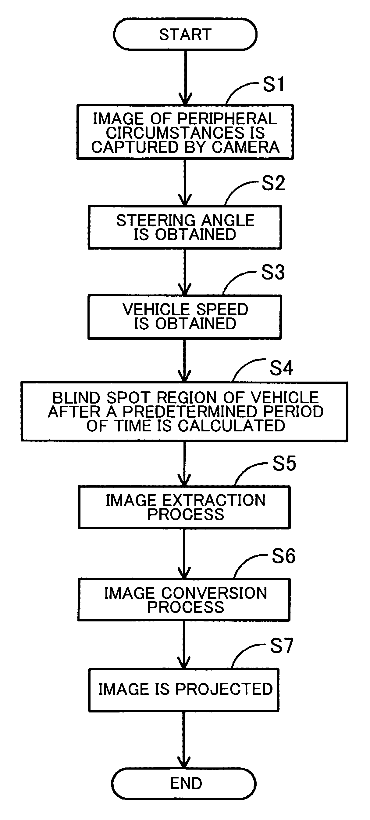
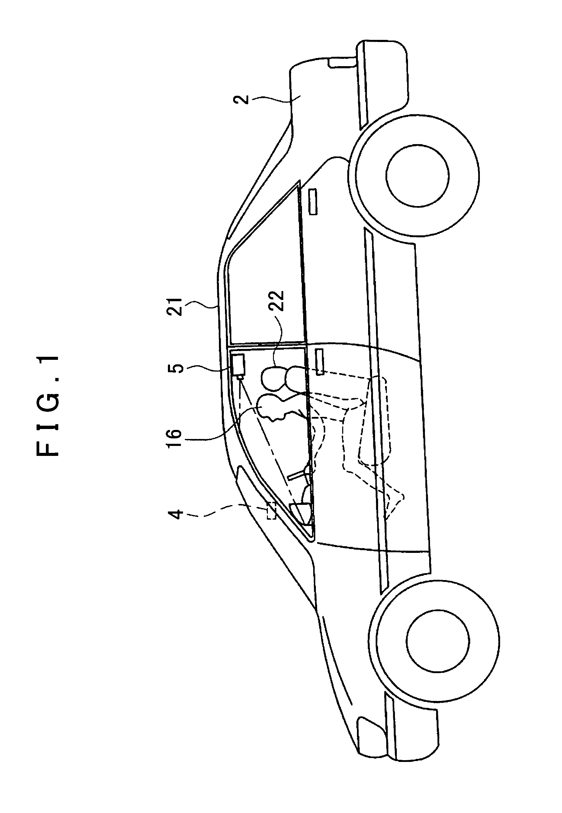
[0025]Hereinafter, an embodiment of a driving support device according to the present invention will be described with reference to the drawings. The driving support device 1 of the present embodiment described hereinbelow is a device in which an image corresponding to a blind spot region of a vehicle is captured by a camera mounted on the exterior of a vehicle and is displayed to a driver in the vehicle, and a blind spot region created by a front pillar of the vehicle is particularly targeted as the blind spot region of the vehicle to be imaged and displayed. Further, as the method of displaying the image corresponding to the blind spot region, projecting the image on the inside interior of the front pillar by a projector is adopted in the present embodiment.

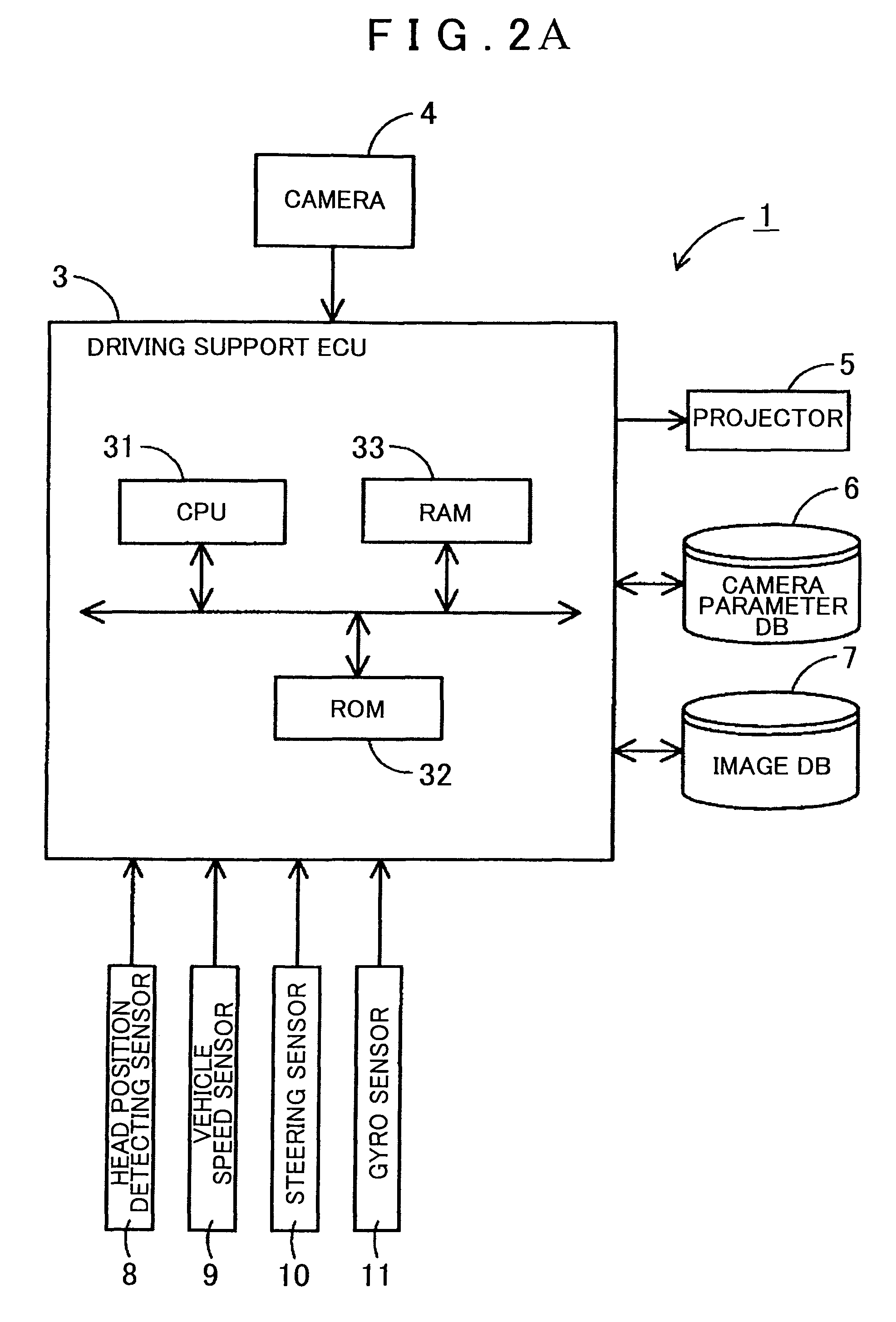
[0026]As shown in FIG. 1, FIG. 2A and FIG. 2B, the driving support device 1 according to the present embodiment has a driving support ECU 3 (including CPU 31 serving as a traveling state obtaining unit 311, an image extracting ...


PUM


Abstract

A driving support device, a driving support method, and a computer program provide an image of the peripheral environment of a vehicle which is captured by a camera. The traveling state of the vehicle is obtained and, based on same, a blind spot region for a driver created by a right front pillar, as it would appear after a predetermined period of time, is calculated by taking into consideration the time lag between capture of an image by the camera and projection of that image by a projector. An image corresponding to the calculated blind spot region is extracted from the image captured by the camera, and the extracted image is projected onto the inside surface of the right front pillar.

Description

INCORPORATION BY REFERENCE[0001]The disclosure of Japanese Patent Application No. 2007-258641 filed on Oct. 2, 2008 including the specification, drawings and abstract is incorporated herein by reference in its entirety.BACKGROUND OF THE INVENTION[0002]1. Field of the Invention[0003]The present invention relates to a driving support device, a driving support method and a computer program for compensating for lack of visibility in a of blind spot of the driver of a vehicle.[0004]2. Description of the Related Art[0005]In recent years, along with the popularization of navigation systems, there has been an increasing use of vehicle image display systems for displaying circumstances around the periphery of a vehicle on interior display devices. For example, positions of other vehicles, obstacles, road markings such as a center line and a stop line, and the like might be displayed.[0006]Here, an area on the periphery of the vehicle which a driver cannot view is the so-called blind spot reg...

Claims


Application Information

Patent Timeline
Patent Type & Authority Patents(United States)
IPC IPC(8): H04N7/00H04N7/18B60R1/00B60R21/00G08G1/16
CPCB60R1/00B60R2300/202B60R2300/30B60R2300/802
Inventor OKABE, HIDEFUMIKOKURYUU, TOMOYUKITAKAGI, MINORU
Owner AISIN AW CO LTD
Why Eureka
Try Eureka